
Microelectromechanical system with reduced speckle contrast

a micro-electromechanical and contrast technology, applied in the field of micro-electromechanical systems with reduced speckle contrast, can solve the problems of reducing affecting the quality of the projected image, and random interference of laser light rays, so as to achieve superior quality and reduce the effect of speckle contras

Inactive Publication Date: 2011-08-11
MEZMERIZ
View PDF14 Cites 17 Cited by
  • Summary
  • Abstract
  • Description
  • Claims
  • Application Information

AI Technical Summary

Benefits of technology

"The present patent application describes a MEMS system that reduces speckle contrast in image projection systems. The system includes micromechanical structures that form a uniform reflective surface on a substrate, an elastic substance coupled to the substrate, and an energy source that applies a voltage to the elastic substance to alter the shape of the surface of the substrate. The micromechanical structures can be cantilevers, bridges, or membranes. The elastic substance can be a piezoelectric or ferroelectric substance. The voltage applied to the elastic substance can be a time-varying voltage. The system can also include a reflective diaphragm connected to the substrate, an elastic substance coupled to the diaphragm, and an energy source that applies a voltage to the elastic substance to vibrate the diaphragm at a frequency of at least 60 Hz. The reflective diaphragm and the substrate can be separated by a distance shorter than a wavelength of light projected onto the substrate. A fluid can be disposed between the reflective diaphragm and the substrate. The patent aims to provide a better quality image projection system by reducing speckle contrast."

Problems solved by technology

However, when laser light reflects off a rough surface, the laser light rays interfere with one another at random.
The constructive and destructive interference causes the reflected light to vary in intensity, a phenomenon commonly known as speckle contrast.
This contrast degrades the quality of the projected image.

Method used


Image

  • Microelectromechanical system with reduced speckle contrast
  • Microelectromechanical system with reduced speckle contrast
  • Microelectromechanical system with reduced speckle contrast

Examples


Embodiment Construction

[0014]The following embodiments of MEMS systems with reduced speckle contrast can be incorporated into or used with image projection systems. An image projection system can include a laser, shaping optics, a reflecting unit, and / or a screen. For example, the laser can project visible light, optionally shaped by shaping optics, onto the MEMS system. As the MEMS system is rotated along one or more axes, the system reflects the laser light over an angular range to project an image. In some image projection systems, the MEMS system directly projects the image onto an external surface, such as a wall. For image projection systems with reflecting units and / or screens, the reflecting unit can redirect the image from the MEMS system onto an external surface or a screen.

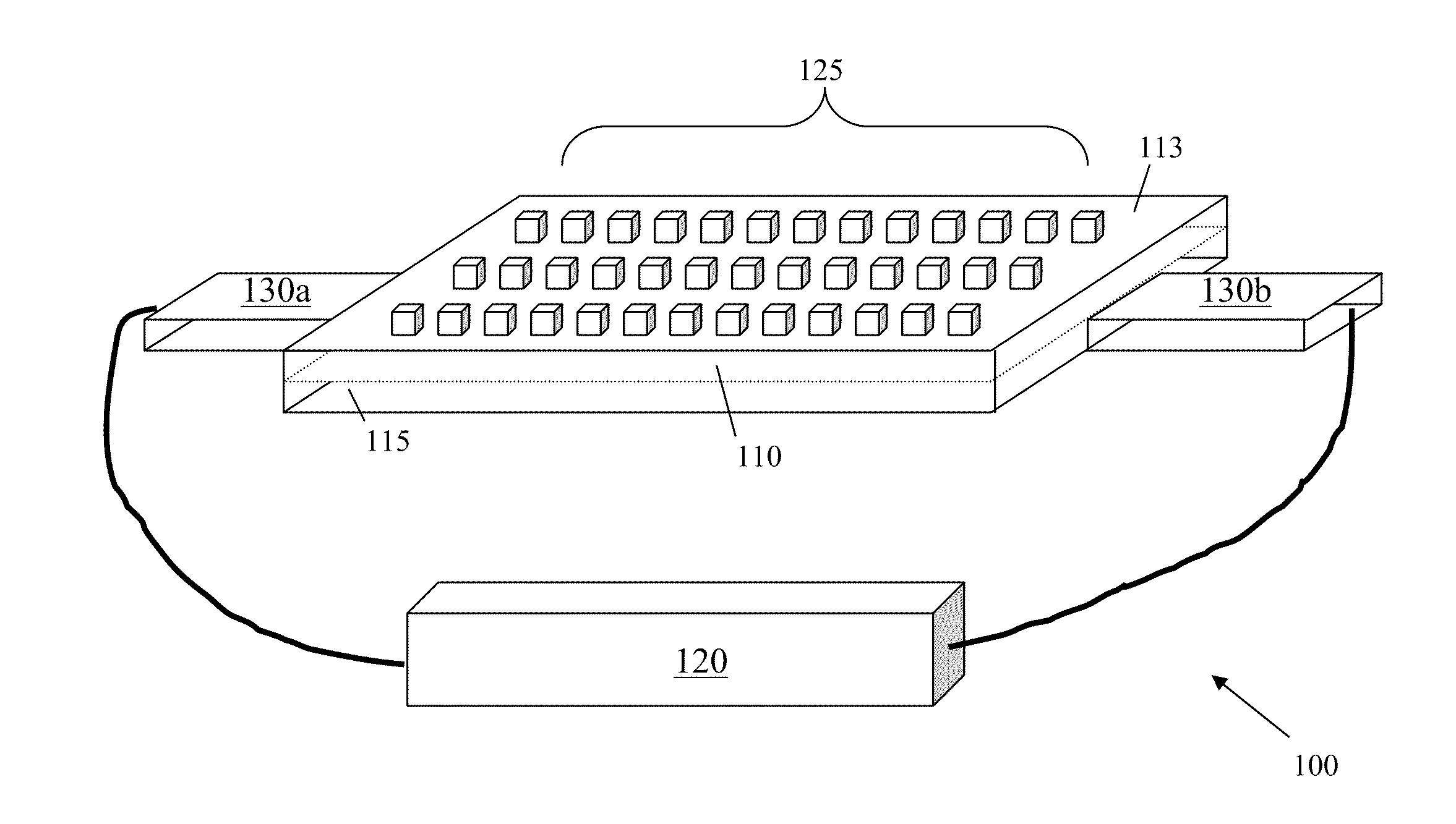
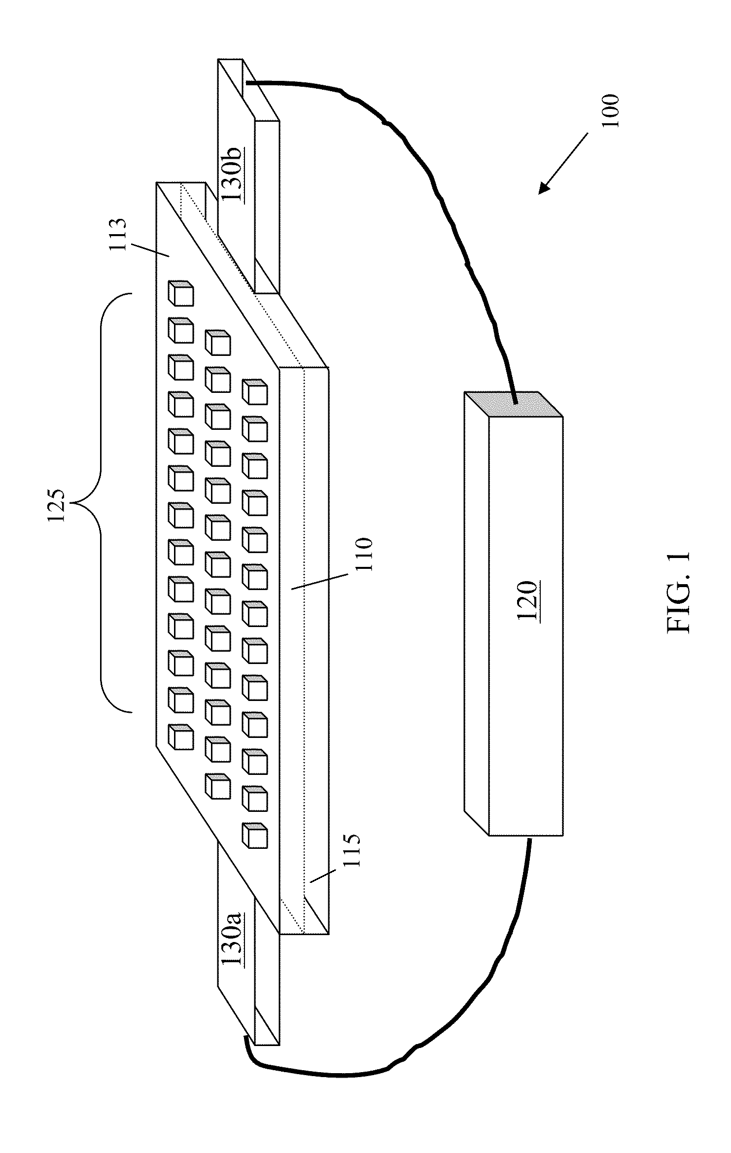
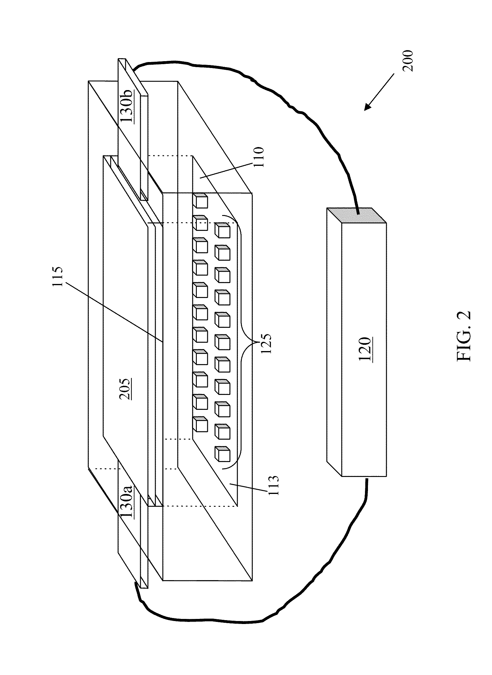
[0015]FIG. 1 depicts an exemplary embodiment of a MEMS system 100 with reduced speckle contrast. The system 100 includes a substrate 110 with a reflective surface 113, an elastic substance 115, and an energy source 120. Micro...


PUM


Abstract

The present disclosure describes, among other things, a reduced speckle contrast microelectromechanical system. One exemplary embodiment includes micromechanical structures configured to form a uniform reflective surface on a substrate, an elastic substance coupled to the substrate, and an energy source that applies a voltage to the elastic substance to alter the shape of the surface of the substrate, for example, by about 10% to about 25% of a wavelength of light projected onto the substrate at a frequency of at least 60 Hz. Another exemplary embodiment includes micromechanical structures formed on a surface of a substrate, a reflective diaphragm connected to the substrate, an elastic substance coupled to the diaphragm, and an energy source that applies a voltage to the elastic substance to vibrate the diaphragm at a frequency of at least 60 Hz.

Description

RELATED APPLICATION[0001]The present application claims priority to U.S. Application No. 61 / 303,574, entitled “Scanning Micromirror with Integrated Laser Speckle Reduction” and filed Feb. 11, 2010, the contents of which are hereby incorporated by reference in their entirety.BACKGROUND[0002]Microelectromechanical systems (also referred to herein as “MEMS systems”) can be used in image projection systems. A laser of an image projection system can project light onto a reflective surface of a MEMS system. By rotating the reflective surface along one or more axes, the reflective surface can reflect the light over an angular range to project an image. However, when laser light reflects off a rough surface, the laser light rays interfere with one another at random. The constructive and destructive interference causes the reflected light to vary in intensity, a phenomenon commonly known as speckle contrast. This contrast degrades the quality of the projected image.SUMMARY OF THE DISCLOSURE[...

Claims


Application Information

Patent Timeline
Patent Type & Authority Applications(United States)
IPC IPC(8): G02B27/48G03B21/28G02B26/08
CPCG02B26/0833G02B27/48H04N9/3197H04N9/3161G03B21/00G03B21/008B81B7/02B81C1/00G02B26/00G02F1/00
Inventor DESAI, SHAHYAAN
Owner MEZMERIZ
Learn More