Clock Recovery Method over Packet Switched Networks based on Network Quiet Period Detection

a clock recovery and packet switched technology, applied in transmission systems, instruments, transmission systems, etc., can solve the problems of maintaining the same level of synchronization, affecting the reliability of the network, so as to reduce the amount of wander and noise, improve the robustness of network packet delay variations, and reduce the effect of pdv

Active Publication Date: 2011-08-11
MICROSEMI SEMICON
View PDF8 Cites 9 Cited by
  • Summary
  • Abstract
  • Description
  • Claims
  • Application Information

AI Technical Summary

Benefits of technology

[0011]Embodiments of the invention take advantage of the certain time periods where network traffic is low or quiet low and as have a result lower PDV. As a result the recovered clock will have the least amount of wander and noise due to network packet delay variations. During these quiet periods, the output of clock recovery algorithm is used to train a time series prediction circuit. At later times when network traffic is heavy time

Problems solved by technology

The main problem is how to maintain the same level of synchronization as in legacy network.
Nonetheless this approach has its own challenges.
One of the main challenges in this synchronization approach is that the timing packets are subjected to packet delay variations (PDV) inherent to any packet switched network.
As a result, at the receiver side, depending on packet delay variations, the recovered reference clock will have high level of jitter and wander, which is not

Method used


Image

  • Clock Recovery Method over Packet Switched Networks based on Network Quiet Period Detection
  • Clock Recovery Method over Packet Switched Networks based on Network Quiet Period Detection
  • Clock Recovery Method over Packet Switched Networks based on Network Quiet Period Detection

Examples


Embodiment Construction

[0021]In the discussion which follows, the following notation is used:

k is index to packet number.

x(k) represents transmitter time stamp for packet

y(k) represents output of the DCO for packet.

z(k) is the raw delay estimate between transmitter and receiver for timing packet

w(k) is the filtered raw delay for timing packet.

fd is the DCO update value.

fc is output of the timing recovery algorithm.

fe is the predicted value by time series predictor.

[0022]Tp is the prediction time.

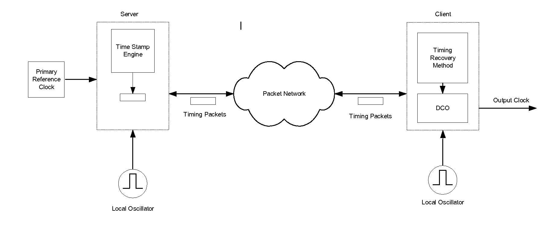
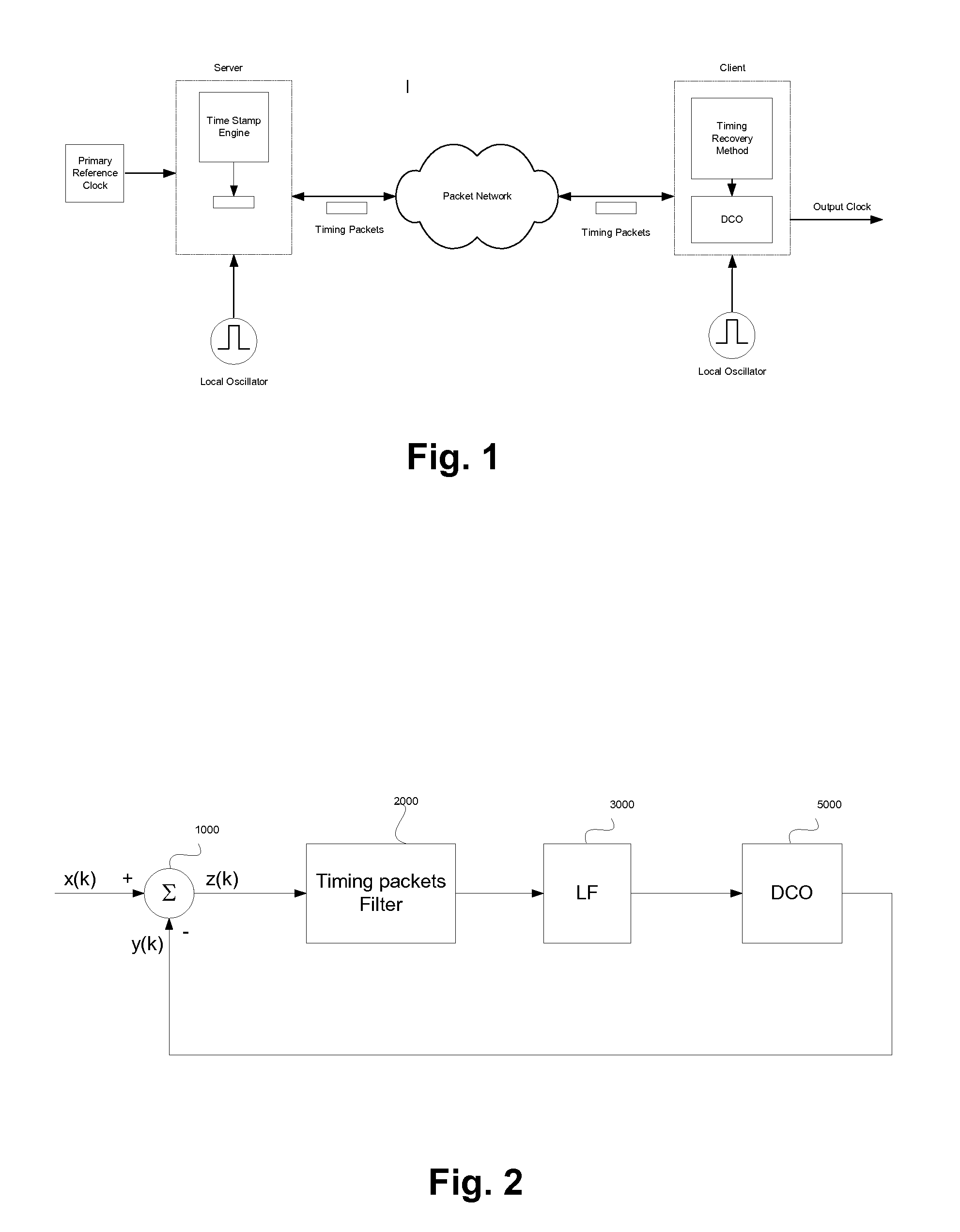
[0023]The prior art circuit shown in FIG. 2 comprises a chain consisting of a adder 1000, a timing packet filter 2000, a loop filter 3000 and a digital controlled oscillator (DCO) 5000 with a feedback loop to the adder 1000. The filter 2000 filters out packets with a large PDV.

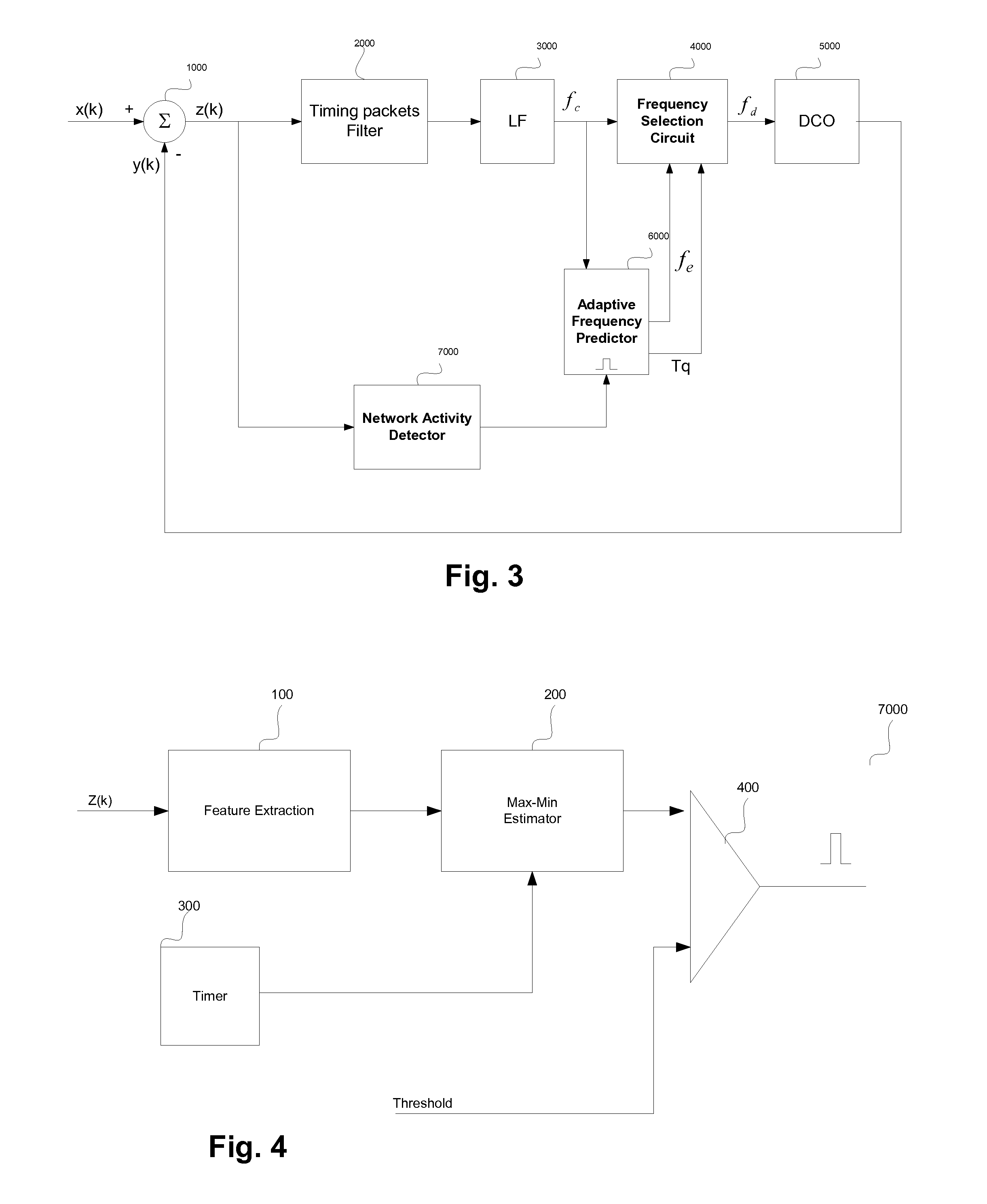
[0024]FIG. 3 shows a top level block diagram of a timing recovery circuit in accordance with an embodiment of the invention. (z(k)) represents raw delays for timestamp k, calculated by subtracting receiver local time stamps (y(k)) generated ...


PUM


Abstract

A method of recovering timing information in a packet network, involves detecting quiet periods in the packet network when network packet delay variation (PDV) is low. A frequency prediction unit is trained during the quiet periods to learn output clock variations of a timing recovery unit to permit the frequency prediction unit to predict frequency update values for a local oscillator during non quiet periods taking into account the historical output clock variations during quiet periods. The output of the frequency prediction unit is used as the active frequency update values during non quiet periods.

Description

FIELD OF THE INVENTION[0001]This invention relates to a method of clock recovery over packet switched networks.BACKGROUND OF THE INVENTION[0002]Synchronization refers to the requirement that transmit and receive ends of a digital communication networks operate at the same clock rate. A network clock located at transmitter node controls the rate at which data is transmitted. A second network clock located at the receiver controls the rate at which data is read. For the receiver to properly interpret incoming data, its clock needs to be synchronized to the transmitter clock.[0003]There are different ways of synchronizing clocks over networks. In some network configurations, which are synchronous, (e.g TDM networks), transmitter clock information can be extracted directly from the data and used in the receiver to synchronize the two clocks. Due to low cost and availability of packet networks, many service providers are looking into transporting legacy services (such as TDM services) ov...

Claims


Application Information

Patent Timeline
IPC IPC(8): H04L12/26
CPCH04J3/0664
Inventor RAHBAR, KAMRAN
Owner MICROSEMI SEMICON
Why Eureka
Try Eureka