Burner inserts for a gas turbine combustion chamber and gas turbine

a gas turbine and combustion chamber technology, applied in the combustion process, hot gas positive displacement engine plants, lighting and heating apparatus, etc., can solve the problems of shortening the useful life and excess supply of cold air at points with an enlarged gap

Inactive Publication Date: 2011-08-18
SIEMENS AG
View PDF10 Cites 19 Cited by
  • Summary
  • Abstract
  • Description
  • Claims
  • Application Information

AI Technical Summary

Benefits of technology

[0018]A gas turbine according to the invention is equipped with at least one gas turbine combustion chamber which is embodied as a gas turbine combustion chamber according to the invention. Furthermore, the gas turbine according to the invention incorporates a cooling fluid reservoir, for example a combu...

Problems solved by technology

These stress the burner insert and shorten its useful life.
With regard to such types of burner inserts, the formation of an uneven gap c...

Method used


Image

  • Burner inserts for a gas turbine combustion chamber and gas turbine
  • Burner inserts for a gas turbine combustion chamber and gas turbine
  • Burner inserts for a gas turbine combustion chamber and gas turbine

Examples


Embodiment Construction

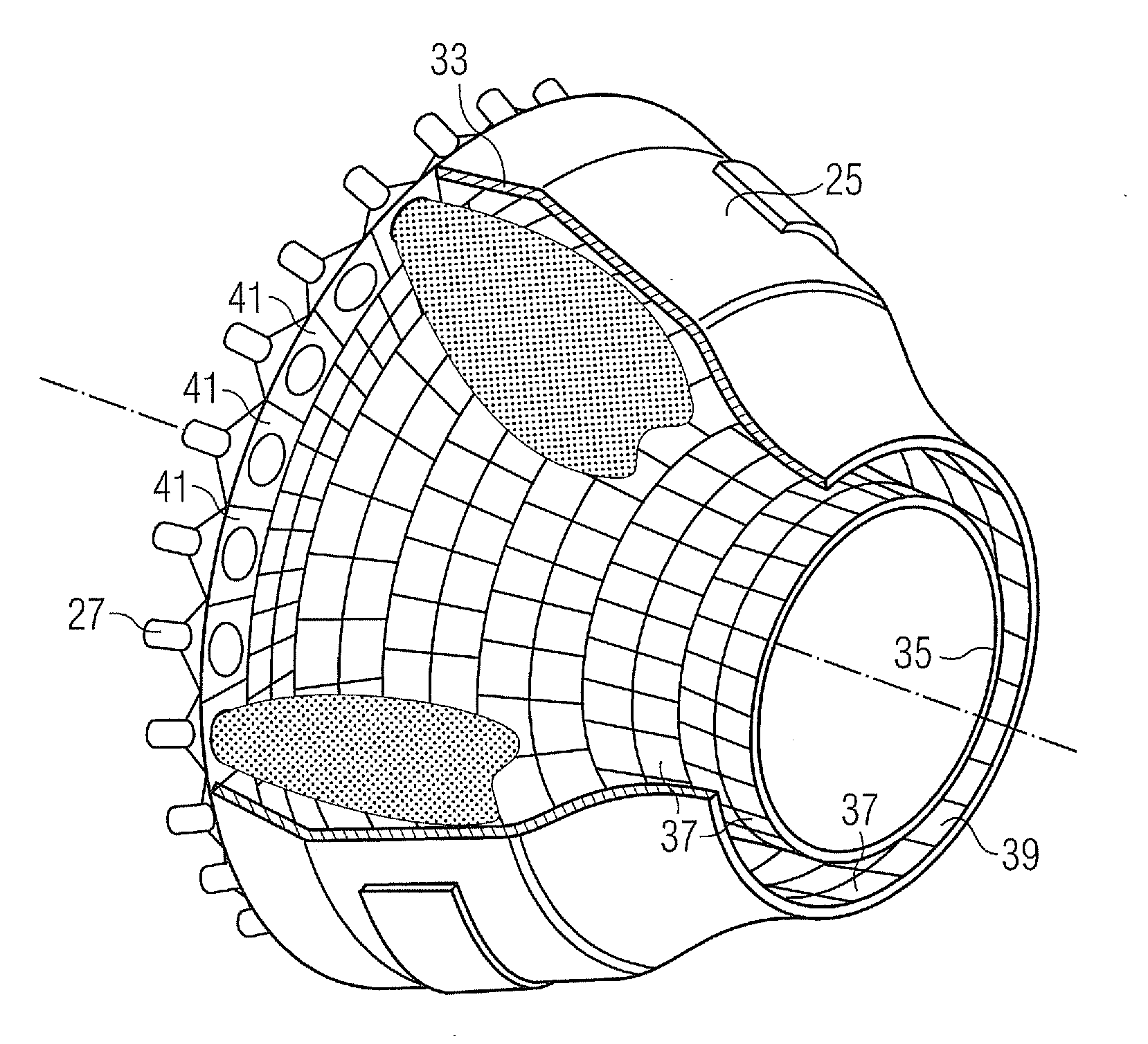
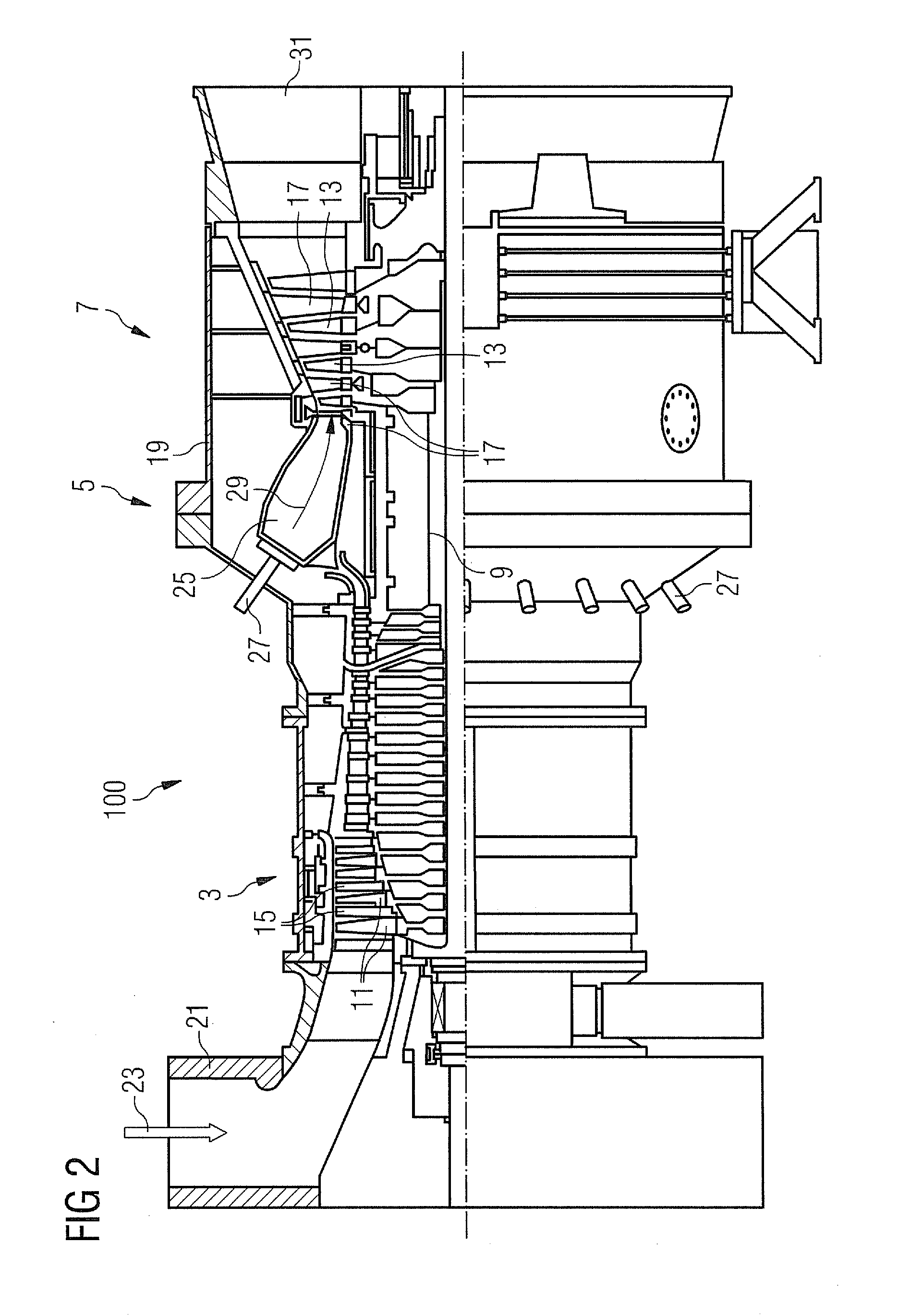
[0027]FIG. 2 shows a longitudinal section of a gas turbine 1 which comprises a compressor section 3, a combustion chamber section 5 and a turbine section 7. A shaft 9 extends through all the sections of the gas turbine 1. In the compressor section 3 the shaft 9 is equipped with rings of compressor blades 11 and in the turbine section 7 with rings of turbine blades 13. Rings of compressor guide vanes 15 are situated between the rings of blades in the compressor section 3 and rings of turbine guide vanes 17 are situated between the rings of blades in the turbine section 7. The guide vanes extend from the housing 19 of the gas turbine unit 1 essentially in the radial direction to the shaft 9.

[0028]During operation of the gas turbine 1, air 23 is drawn in through an air inlet 21 of the compressor section 3 and compressed by the compressor blades 11. The compressed air is fed to a combustion chamber 25 arranged in the combustion chamber section 5, which in the present exemplary embodimen...


PUM


Abstract

A burner insert for a gas turbine combustion chamber is provided. The burner insert includes a burner insert wall including a cold side and a hot side, an edge delimiting the burner insert wall. The edge includes an edge bar extending at least partially circumferentially and projecting beyond the cold side. A burner opening for inserting a burner is formed in the burner insert wall.

Description

CROSS REFERENCE TO RELATED APPLICATIONS[0001]This application is the US National Stage of International Application No. PCT / EP2009 / 061854, filed Sep. 14, 2009 and claims the benefit thereof. The International Application claims the benefits of European Patent Office application No. 08018907.9 EP filed Oct. 29, 2008. All of the applications are incorporated by reference herein in their entirety.FIELD OF INVENTION[0002]The present invention relates to a burner insert for a gas turbine combustion chamber, which comprises a burner opening for inserting a burner. The invention also relates to a gas turbine.BACKGROUND OF INVENTION[0003]Gas turbine combustion chambers comprise a burner-side end and a turbine-side end. The turbine-side end is open and enables the hot combustion gases produced in the combustion chamber to flow out to the turbine. At the burner-side end a burner insert is often present which comprises a heat-resistant hot side and a cooled cold side. The burner is inserted in...

Claims


Application Information

Patent Timeline
IPC IPC(8): F23R3/42F02C3/14
CPCF23R3/002F23R2900/03042F23R3/10
Inventor BOTTCHER, ANDREASKLUGE, ANDREKRIEGER, TOBIASMEISL, JURGENSCHILDMACHER, KAI-UWE
Owner SIEMENS AG
Why Eureka
Try Eureka