Pneumatic tire

a pneumatic tire and tire body technology, applied in the field of pneumatic tires, can solve problems such as curing failure, and achieve the effects of preventing curing failure, preventing air permeation from failing, and high rigidity

Inactive Publication Date: 2011-08-18
YOKOHAMA RUBBER CO LTD
View PDF12 Cites 16 Cited by
  • Summary
  • Abstract
  • Description
  • Claims
  • Application Information

AI Technical Summary

Benefits of technology

[0009]In the present invention, a pneumatic tire has an end portion, on a tire cavity side, of each chafer for protecting a corresponding bead part being inserted between a carcass layer and an inner liner layer. When the inner liner layer is formed of a thermoplastic resin or a thermoplastic elastomer composition, a tie rubber layer is disposed between the inner liner layer and the chafer. Thereby, air inclusion is prevented from being generated between the inner liner layer and the tie rubber layer in the bead part. Thus, the tire is capable of preventing curing failure attributable to the it inclusion.
[0010]In the present invention, the position of each lower end of the inner liner layer is preferably located outward of a corresponding bead toe in a tire radial direction. This is because of the following reason. An inner liner layer with a matrix of a thermoplastic resin has a higher rigidity than that formed of a butyl rubber. As a result, if the inner liner layer has such a dimension that the inner liner layer extends beyond the bead toe, a wrinkle is formed in the inner liner layer when a carcass layer is wound up around a bead core in building a tire. Meanwhile, the position of each lower end of the liner layer is preferably located within a region not more than 35% of a cross-sectional height of the tire. By this, the air permeation preventive function can be sufficiently demonstrated.
[0011]The position of each lower end of the tie rubber layer is preferably located at the same level as the position of the corresponding lower end of the inner liner layer, or located inward thereof in the tire radial direction. This makes it possible to more surely avoid air inclusion. In addition, a height ht measured in the tire radial direction from each bead toe to the position in the corresponding lower end of tine tie rubber layer and a height hb measured in the tire radial direction from the bead. toe to the position of an innermost diameter of the corresponding bead core preferably have a relationship of ht≧hb / 2. This is because of the following reason. If a tie rubber layer generally not blended with an antioxidant is present in the vicinity of the bead toe without being covered with an inner liner layer, the physical properties of this portion are deteriorated through ozone degradation or the like. Thereby, the bead toe is easy to crack when the tire is fitted onto or removed from a rim. By satisfying the relationship of ht≧hb / 2, it is possible to prevent the bead toe from cracking when the tire is fitted onto or removed from the rim. Furthermore, in order to prevent the bead toe from cracking when the tire is fitted onto or removed from the rim, it is effective to blend a rubber composition forming the tie rubber layer and an antioxidant.

Problems solved by technology

This brings about a problem of curing failure.

Method used


Image

  • Pneumatic tire
  • Pneumatic tire
  • Pneumatic tire

Examples


examples

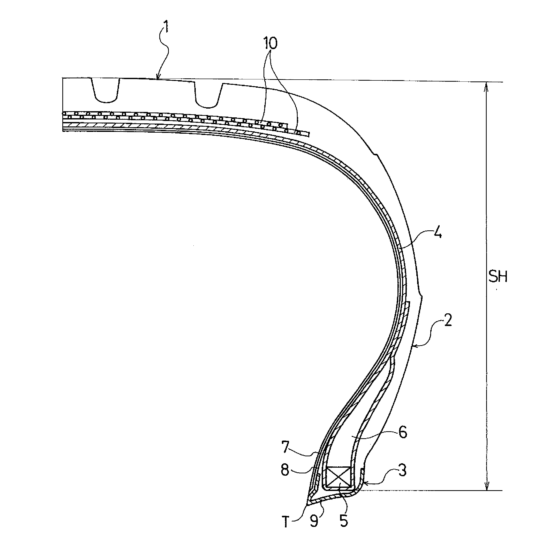
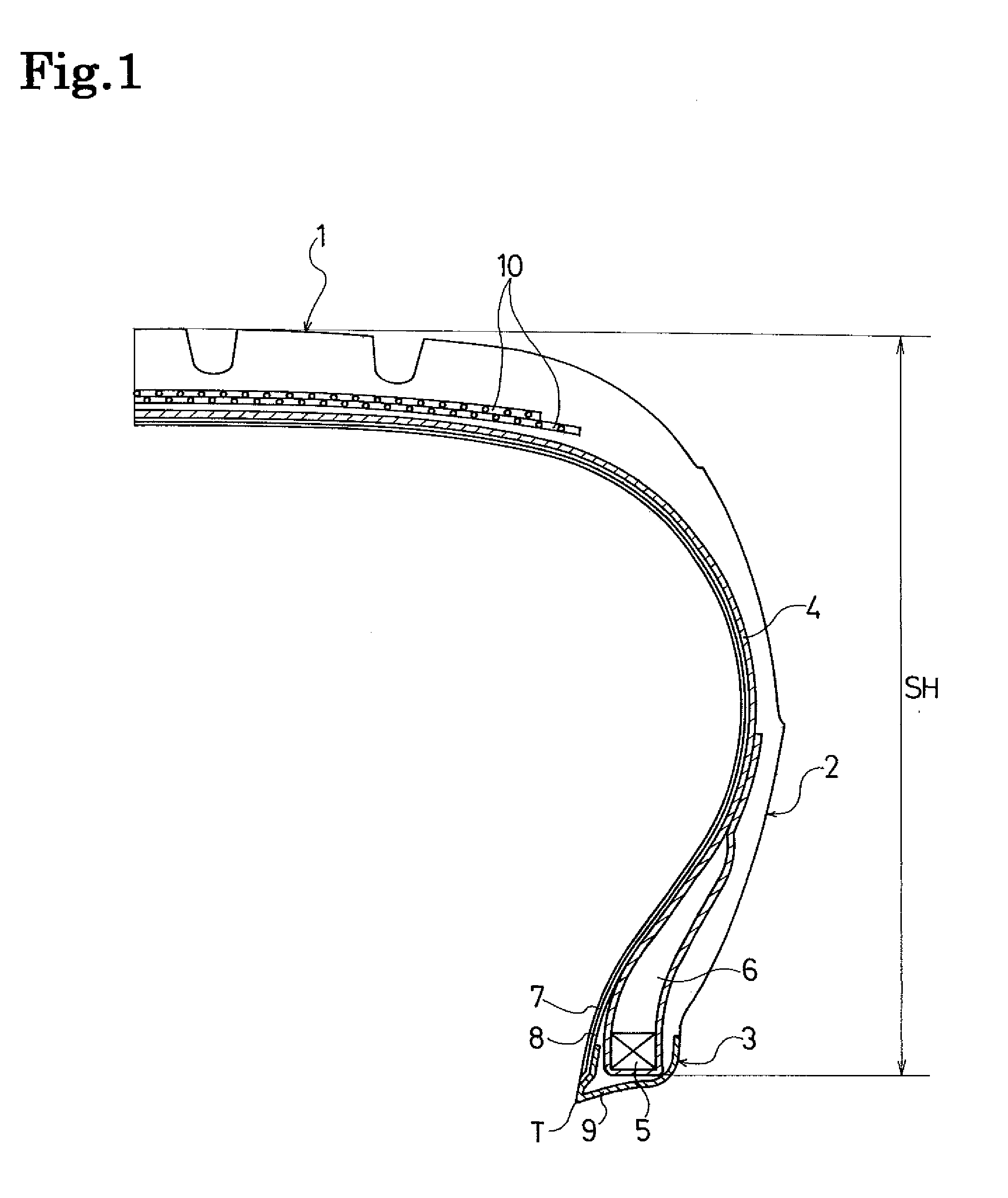
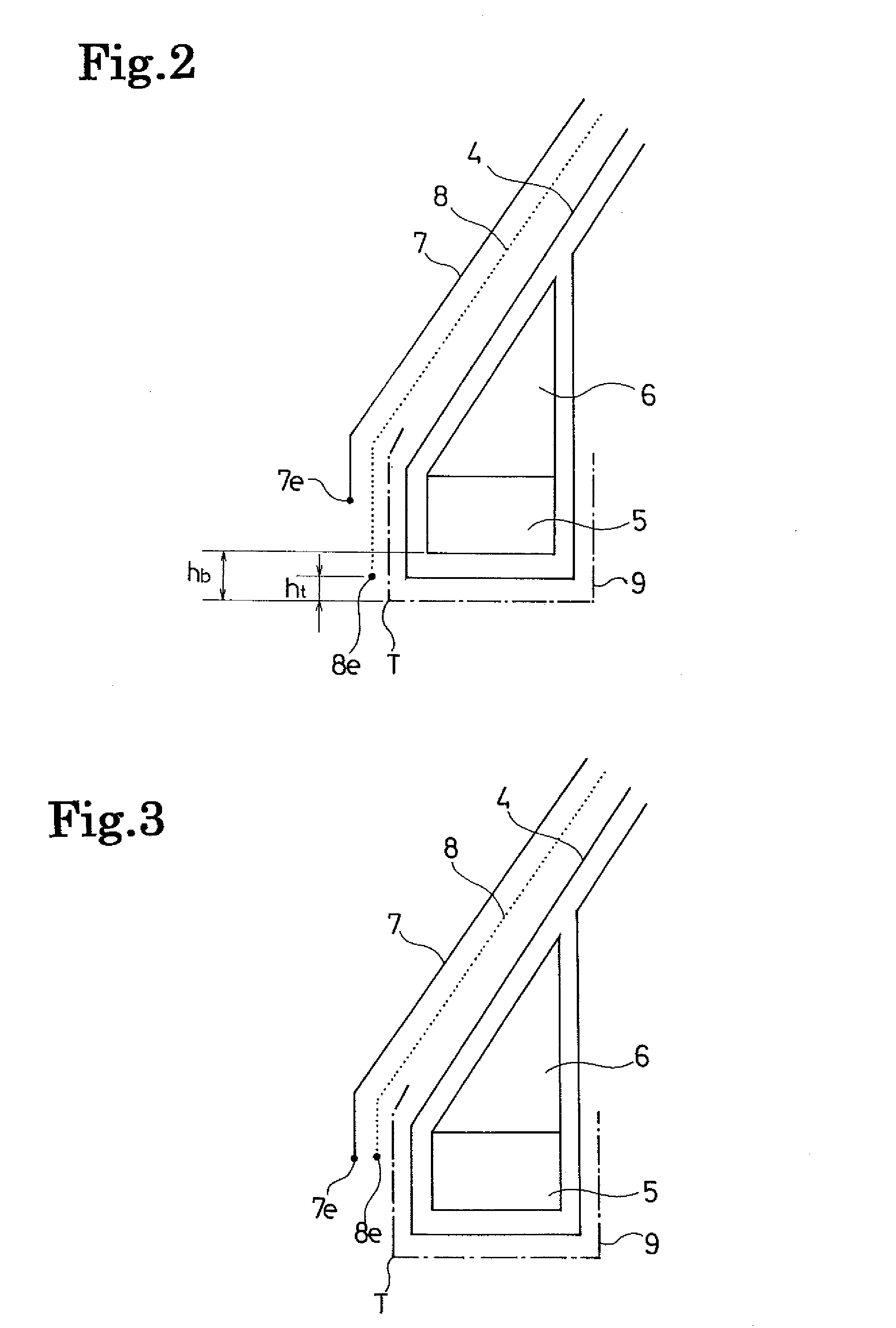
[0037]Pneumatic tires of Conventional Example and Examples 1 to 5 were prepared as follows. Each tire had a tire size of 225 / 40R18. Each tire included: a carcass layer laid between a pair of bead parts; an inner liner layer disposed at a tire cavity side of the carcass layer; a tie rubber layer interposed between the carcass layer and the inner liner layer; and chafers protecting the respective bead parts, an end portion on a tire cavity side of each chafer being inserted between the carcass layer and the inner liner layer. The inner liner layer was formed of a thermoplastic elastomer composition containing a blend of a thermoplastic resin (nylon 6,66) and an elastomer (brominated butyl rubber). The arrangement of the tie rubber layer and the chafers was made different among these examples. Note that: the thickness of the inner liner layer was 50 μm; the thickness of the tie rubber layer was 500 μm; and the thickness of the chafers was 0.7 mm.

[0038]In the tire of Conventional Exampl...


PUM


Abstract

Provided is a pneumatic tire: which has an inner liner layer formed of a thermoplastic resin or a thermoplastic elastomer composition containing a blend of a thermoplastic resin with an elastomer; and which, despite of this, is free from air inclusion in bead parts and is capable of preventing curing failure attributable to the air inclusion. The pneumatic tire of the present invention includes: a carcass layer laid between a pair of bead parts; an inner liner layer disposed at a tire cavity side of the carcass layer; a tie rubber layer interposed between the carcass layer and the inner liner layer; and chafers for protecting the respective bead parts, an end portion on a tire cavity side of each chafer being inserted between the carcass layer and the inner liner layer. In the pneumatic tire, the inner liner layer is formed of a thermoplastic resin or a thermoplastic elastomer composition containing a blend of a thermoplastic resin with an elastomer; and the tie rubber layer is disposed between the inner liner layer and the chafer.

Description

TECHNICAL FIELD[0001]The present invention relates to a pneumatic tire including an inner liner layer formed of a thermoplastic resin or a thermoplastic elastomer composition containing a blend of a thermoplastic resin and an elastomer. More specifically, the present invention relates to a pneumatic tire which is tree from air inclusion in bead parts and thus prevents curing failure attributable to the air inclusion.BACKGROUND ART[0002]Recently, it is proposed that a. film layer formed of a thermoplastic resin or a thermoplastic elastomer composition containing a blend of a thermoplastic resin and an elastomer be disposed as an inner liner layer on a tire inner surface.[0003]In such a pneumatic tire, a carcass layer is laid between a pair of bead parts. An inner liner layer is disposed at a tire cavity side of the carcass layer. A tie rubber layer is interposed between the carcass layer and the inner liner layer to improve the adhesiveness between the two. Moreover, when chafers are...

Claims


Application Information

Patent Timeline
Patent Type & Authority Applications(United States)
IPC IPC(8): B60C15/06
CPCB29D2030/0682B60C5/14Y10T152/10828B60C2005/145B60C2015/0614B60C15/06
Inventor MATSUDA, JUNHASHIMURA, YOSHIAKI
Owner YOKOHAMA RUBBER CO LTD
Why Eureka
Try Eureka