Liquid crystal display device and electronic device
a liquid crystal display device and electronic device technology, applied in the direction of electric digital data processing, instruments, computing, etc., can solve the problems of insufficient lowering of power consumption of liquid crystal display devices, deterioration of displayed image, and inability to keep the voltage between pixel electrodes and common electrodes constant in some cases, so as to achieve less deterioration of image quality and power consumption reduction
- Summary
- Abstract
- Description
- Claims
- Application Information
AI Technical Summary
Benefits of technology
Problems solved by technology
Method used
Image
Examples
embodiment 1
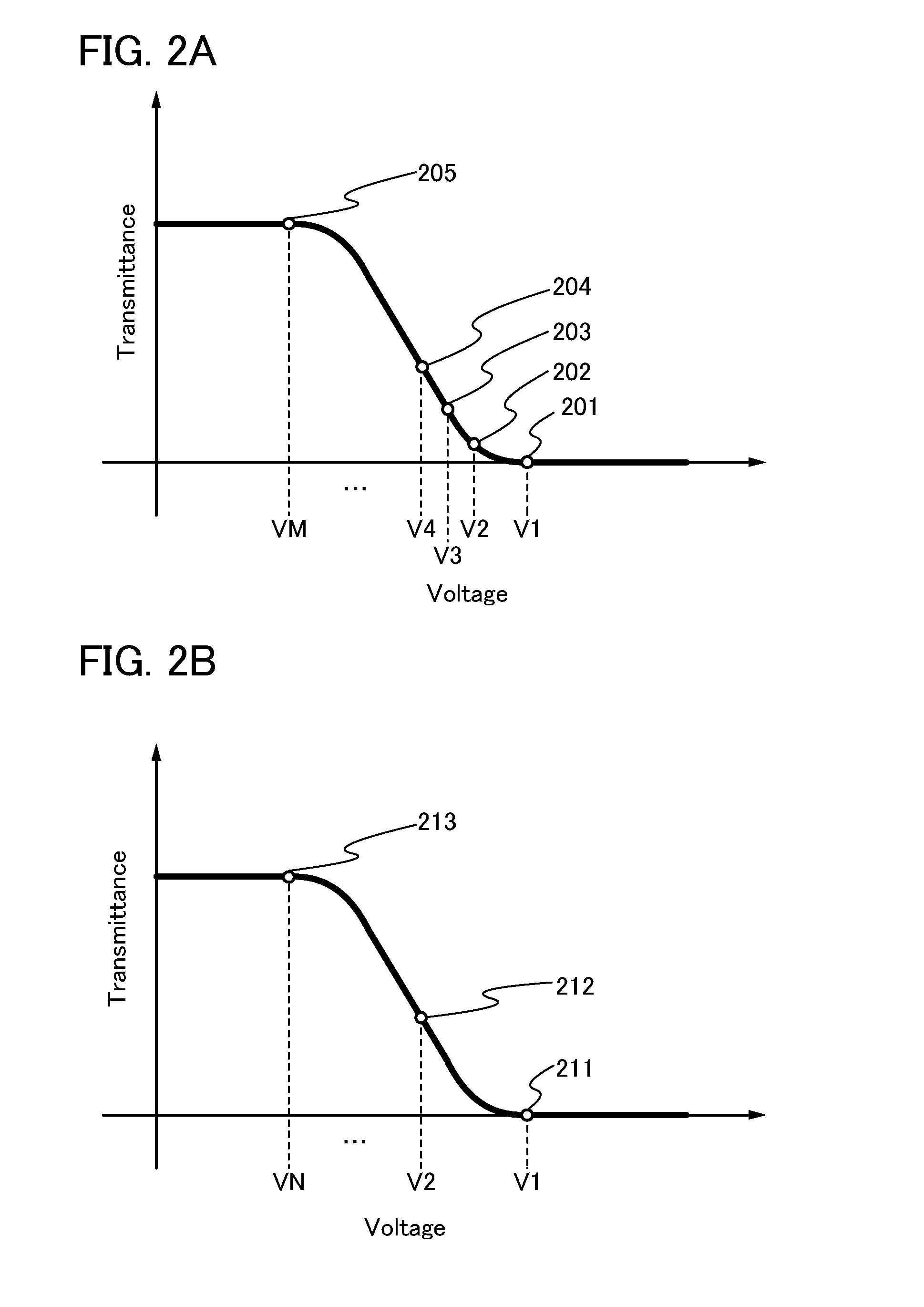
In this embodiment, a liquid crystal display device will be described with reference to a schematic diagram, a block diagram, and a diagram for illustrating the relation between characteristics of a liquid crystal element and a gray level number.
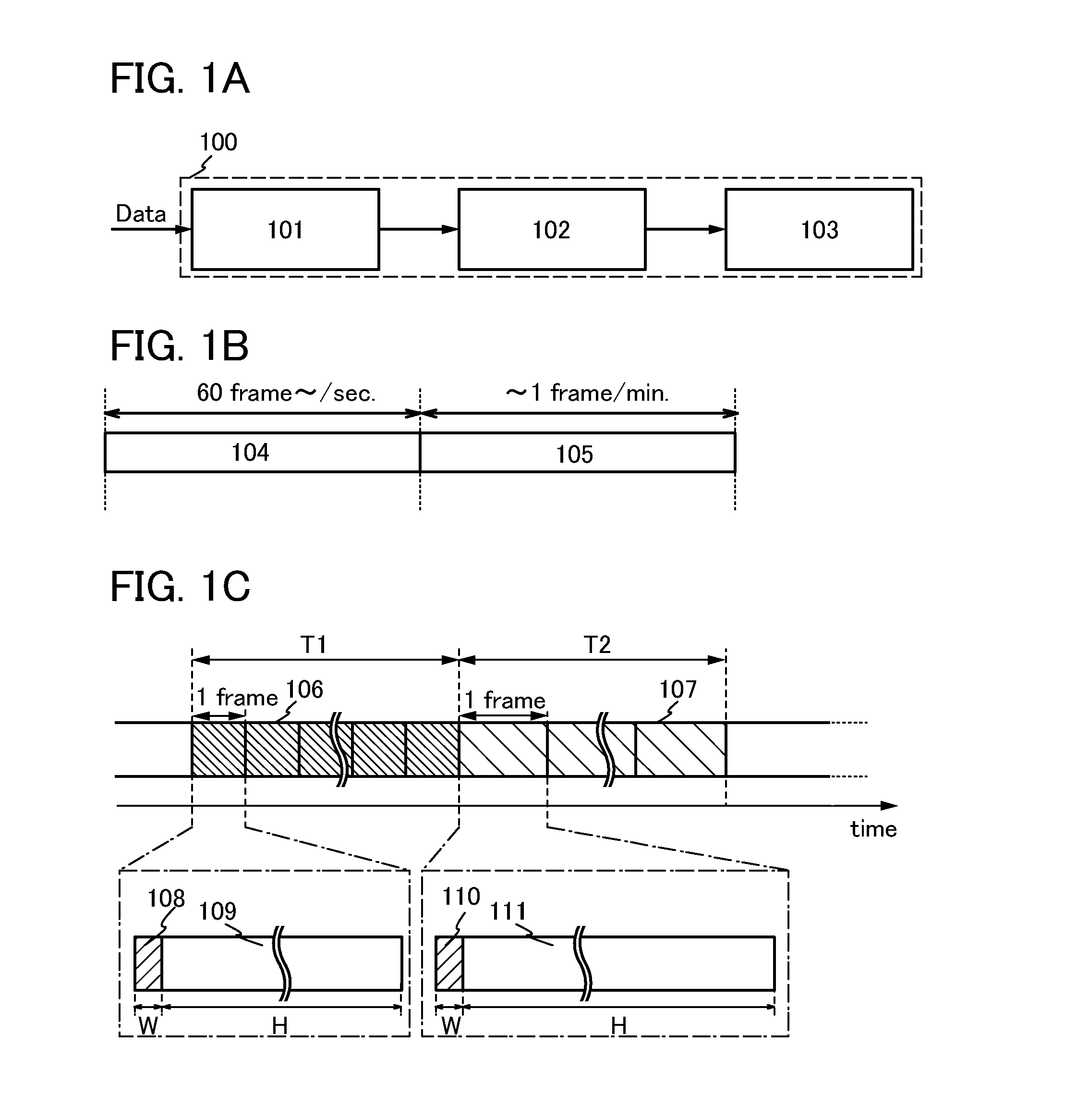
The liquid crystal display device relating to this specification will be described with reference to FIGS. 1A to 1C which are the simple block diagram of the liquid crystal display device and the schematic diagrams for illustrating a liquid crystal display device.
A liquid crystal display device 100 illustrated in FIG. 1A includes a timing controller (also referred to as a timing control circuit) 101, a driver circuit 102, and a display portion 103. The timing controller 101 is supplied with an image signal Data from the outside.
The timing controller 101 in FIG. 1A has a function of changing a refresh rate in accordance with a gray level number of the image signal Data (i.e., a gray level number of an image which is displayed with the image s...
embodiment 2
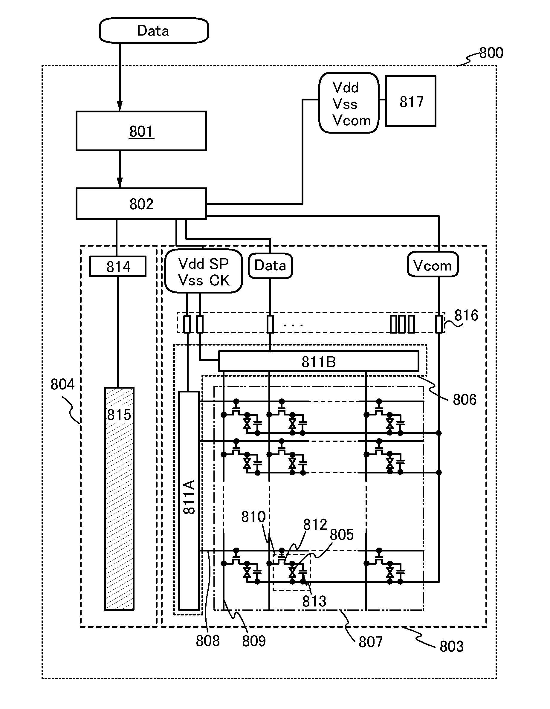
In this embodiment, a liquid crystal display device of the present invention and one mode of a liquid crystal display device which can achieve low power consumption will be described with reference to FIG. 5, FIG. 6, FIGS. 7A and 7B, and FIG. 8.
A block diagram of FIG. 5 illustrates a structure of a liquid crystal display device 800 described in this embodiment. The liquid crystal display device 800 includes an image process circuit 801, a timing controller 802, and a display panel 803. In the case of a transmissive liquid crystal display device or a transflective liquid crystal display device, a backlight portion 804 is additionally provided as a light source.
The liquid crystal display device 800 is supplied with the image signal (the image signal Data) from an external device connected thereto. Note that power supply potentials (a high power supply potential Vdd, a low power supply potential Vss, and a common potential Vcom) are supplied when a power source 817 of the liquid crysta...
embodiment 3
In this embodiment, an example of a transistor which can be applied to a liquid crystal display device disclosed in this specification will be described.
FIGS. 9A to 9D each illustrate an example of a cross-sectional structure of a transistor.
A transistor 1210 illustrated in FIG. 9A is a kind of bottom-gate structure transistor and is also called an inverted staggered transistor.
The transistor 1210 includes, over a substrate 1200 having an insulating surface, a gate electrode layer 1201, a gate insulating layer 1202, a semiconductor layer 1203, a source electrode layer 1205a, and a drain electrode layer 1205b. An insulating layer 1207 is provided to cover the transistor 1210 and be stacked over the semiconductor layer 1203. A protective insulating layer 1209 is provided over the insulating layer 1207.
A transistor 1220 illustrated in FIG. 9B has a kind of bottom-gate structure called a channel-protective type (channel-stop type) and is also referred to as an inverted staggered transis...
PUM
| Property | Measurement | Unit |
|---|---|---|
| frequency | aaaaa | aaaaa |
| band gap | aaaaa | aaaaa |
| band gap | aaaaa | aaaaa |
Abstract
Description
Claims
Application Information
 - R&D
- Intellectual Property
- Life Sciences
- Materials
- Tech Scout
- Unparalleled Data Quality
- Higher Quality Content
- 60% Fewer Hallucinations
Browse by: Latest US Patents, China's latest patents, Technical Efficacy Thesaurus, Application Domain, Technology Topic, Popular Technical Reports.
© 2025 PatSnap. All rights reserved.Legal|Privacy policy|Modern Slavery Act Transparency Statement|Sitemap|About US| Contact US: help@patsnap.com


