Solid-state image sensor

a solid-state image and sensor technology, applied in the field of solid-state image sensors, can solve the problems of difficult to realize such a structure, provide a structure, and spread of light, and achieve the effects of reducing crosstalk, excellent color reproducibility, and high definition capabilities

Inactive Publication Date: 2011-08-18
CANON KK
View PDF8 Cites 11 Cited by
  • Summary
  • Abstract
  • Description
  • Claims
  • Application Information

AI Technical Summary

Benefits of technology

[0006]On the other hand, the method disclosed in the above-cited Japanese Patent Application Laid-Open No. 2008-41847 cannot suppress the spread of light being propagated in the inside of the silicon substrate 1101 in the transversal direction. This method suppresses the spread of the electric field intensity distribution of the spot of light focused by a lens by means of a phase shift mask of the type that is being popularly employed in the field of lithography technology to raise the resolution. However, such means cannot reduce the angle of diffraction of light being transmitted through the mask. Rather, with the method of the above-cited Japanese Patent Application Laid-Open No. 2008-41847, the spreading angle of light being propagated in the inside of the silicon substrate 1101 is increased to further spread light in the transversal direction when the electric field amplitude distribution shows positive regions and negative regions that are intermingled on the silicon substrate surface 1101. When a structure is arranged on the silicon substrate surface 1110, it can damage the photoelectric conversion section 1102 to give rises to a problem of producing noises.
[0007]In view of the above-identified circumstances, the object of the present invention is to provide a solid-state image sensor that can suppress the crosstalk produced on and in a silicon substrate and shows an excellent color reproducibility and high definition capabilities.
[0009]Thus, according to the present invention, it is possible to realize a solid-state image sensor that can suppress the crosstalk produced on and in a silicon substrate and shows an excellent color reproducibility and high definition capabilities.

Problems solved by technology

However, while the optical waveguide of FIG. 15A can efficiently guide light to the surface of the silicon substrate, it is accompanied by a problem that light spreads to adjacent pixel regions under the influence of diffraction in the inside of the silicon substrate to give rise to crosstalk. FIG. 15B is a graph showing the penetration depth (propagation distance where the intensity falls to 1 / e) relative to the wavelength.
It is difficult from the design point of view to provide a structure that optically separates adjacent pixels in the inside of a silicon substrate.
Additionally, it is difficult to realize such a structure because it inevitably increases the noise level.
On the other hand, the method disclosed in the above-cited Japanese Patent Application Laid-Open No. 2008-41847 cannot suppress the spread of light being propagated in the inside of the silicon substrate 1101 in the transversal direction.
However, such means cannot reduce the angle of diffraction of light being transmitted through the mask.
When a structure is arranged on the silicon substrate surface 1110, it can damage the photoelectric conversion section 1102 to give rises to a problem of producing noises.

Method used


Image

  • Solid-state image sensor
  • Solid-state image sensor
  • Solid-state image sensor

Examples


embodiment 1

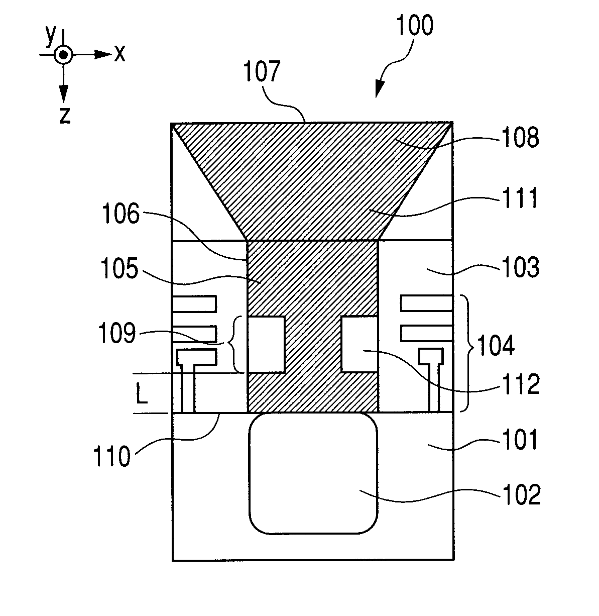
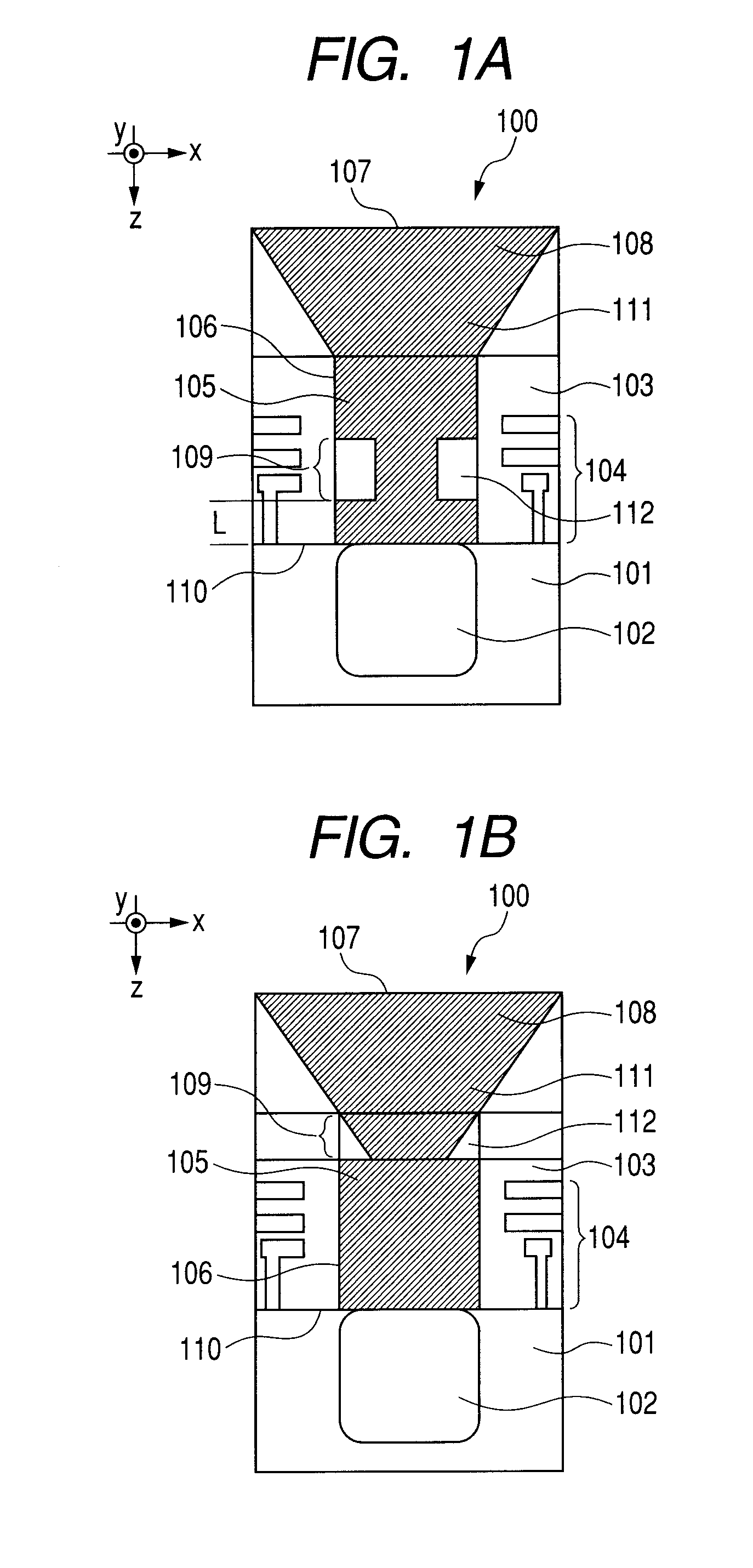
[0026]The solid-state image sensor of Embodiment 1 of the present invention will be described by referring to FIG. 1A. The solid-state image sensor of this embodiment includes pixel units having a substrate including a photoelectric conversion section in the inside and an optical waveguide arranged at the light incident side of the substrate so as to lead incident light converted into the guided mode that the optical waveguide possesses and being propagated through the optical waveguide to the photoelectric conversion section.

[0027]More specifically, the solid-state image sensor of this embodiment includes a plurality of pixel units 100 arranged to form a matrix. Each of the pixel units 100 has a silicon substrate 101 and a photoelectric conversion section 102 arranged in the inside of the silicon substrate 101. Additionally, the pixel unit 100 has a clad section (interlayer insulating section) 103 formed of a transparent material on the silicon substrate 101 and a wiring section 10...

embodiment 2

[0079]Now, the solid-state image sensor of Embodiment 2 of the present invention will be described below by referring to FIG. 9A. The solid-state image sensor of this embodiment includes a plurality of pixel units 200 arranged in the form of a matrix. The pixel units 200 of this embodiment have a structure that differs from the pixel unit 100 of Embodiment 1 illustrated in FIG. 1A only in terms of the mode conversion section. If the refractive index of the core section 105 is n1 and the refractive index of the clad section 103 is n2, the mode conversion section 201 is formed by arranging a mode conversion structure 202 having refractive index n3 (105 in the optical waveguide 106. Note that it is sufficient for the mode conversion structure 202 to be made of a material having a refractive index different from the core section 105. It is assumed here that the mode conversion structure 202 has a refractive index lower than that of the core section 105. Assume that the width of the core...

embodiment 3

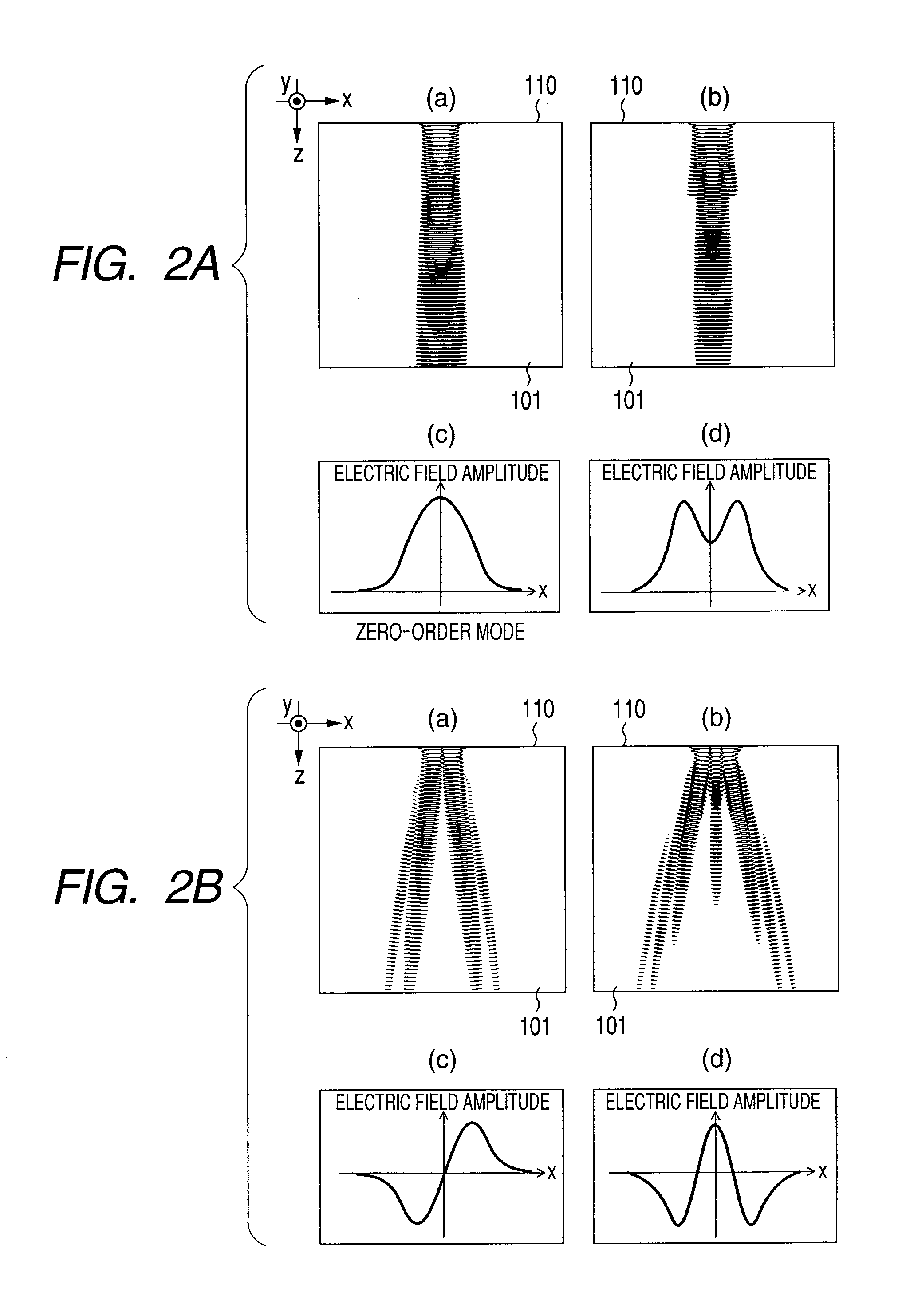
[0093]The solid-state image sensor of Embodiment 3 of the present invention will be described below by referring to FIG. 13A. The solid-state image sensor of this embodiment includes a plurality of pixel units 300 arranged in the form of a matrix. Unlike the pixel unit 100 of Embodiment 1 illustrated in FIG. 1A, the mode conversion structure 112 of the mode conversion section 109 of the pixel units 300 of this embodiment is made of metal. In FIGS. 1A and 13A, the components having a same function are denoted by a same reference symbols. In this embodiment, the optical waveguide 106 illustrated in FIG. 13A has eigenmodes same as those illustrated in FIG. 3A for Embodiment 1. Light entering the device from the incident surface 107 is converted into the guided mode that is expressed by superposing the eigenmodes for propagation. Light is propagated through the core section 105 in a concentrated manner so as to be protected against the crosstalk that arises on the silicon substrate 101....


PUM


Abstract

A solid-state image sensor comprises a pixel unit having a substrate including therein a photoelectric conversion section and an optical waveguide arranged on a light incident side of the substrate so as to guide an incident light converted into a guided mode of the optical waveguide and being propagated through the optical waveguide to the photoelectric conversion section. The optical waveguide has a mode conversion section for changing a propagation state of the incident light such that the incident light being propagated through the optical waveguide has an electric field amplitude distributed with the same sign at a light incident surface of the substrate.

Description

TECHNICAL FIELD[0001]The present invention relates to a solid-state image sensor. More particularly, the present invention relates to a solid-state image sensor to be suitably used for a digital video camera or a digital still camera.BACKGROUND ART[0002]The size of each pixel of solid-state image sensors being used in digital video cameras and digital still cameras has been downsized year by year as the number of pixels of such a camera has been increased. As a result, the area of the photoelectric conversion section of the camera has been reduced, and the aspect ratio (depth / width) of the pixel structure has been raised. As the area of the photoelectric conversion section is reduced, there arises a problem of reduction in light receiving sensitivity. As the aspect ratio of the pixel structure is raised, there arise concerns that the F-value of the on-chip lens rises to reduce the focusing efficiency and produce a problem of crosstalk of light leaking to adjacent pixels.[0003]To dat...

Claims


Application Information

Patent Timeline
Patent Type & Authority Applications(United States)
IPC IPC(8): H04N5/335
CPCH01L27/14625H01L27/14687H01L27/14685H01L27/14632
Inventor KATO, TAROTAKAGI, AKINARI
Owner CANON KK
Why Eureka
Try Eureka