Eureka AIR delivers breakthrough ideas for toughest innovation challenges, trusted by R&D personnel around the world.

Modular lighting fixture with improved device for connecting the arms to the respective support

a technology of modular lighting and arms, applied in the direction of electric lighting, fixed installation, lighting apparatus, etc., can solve the problems of limiting the overall dimension, affecting the effect of lighting effect, etc., to achieve the effect of facilitating packaging, transportation and storage, and reducing the overall dimension

Inactive Publication Date: 2011-08-18
VOLTOLINA FRANCESCO
View PDF8 Cites 5 Cited by
  • Summary
  • Abstract
  • Description
  • Claims
  • Application Information

AI Technical Summary

Benefits of technology

[0010]More in particular, the object of the present invention is to provide a modular lighting fixture wherein the arms are connected to the respective support so as to considerably reduce the overall dimensions compared to the known solutions. A further and consequent object of the invention is to provide a modular lighting fixture suitable for being easily packaged, transported and stored thanks to its limited dimensions.
[0011]A further object of the invention is to provide a modular lighting fixture wherein the arms, once connected to the respective support, are effectively stabilised and safe from possible bending which, over time, may give rise to cracks and breakage of the same arms.
[0013]A further object of the invention is to provide the users with a modular lighting fixture intended for ensuring high levels of resistance and reliability over time, also such as to be easily and inexpensively constructed.

Problems solved by technology

The finished chandelier, that is, assembled in it components, exhibits the further problem of handling, for the transport and installation thereof at the end user.
Especially in the case of large sized chandeliers, with multiple and greatly projecting arms, the transportation is difficult and the arms are thus removed from the relative support, in order to substantially limit the overall dimensions for transportation.
In this case it is then required to assemble the various elements again and restore the mechanical and electrical connections; both the preventive removal and the assembly after transportation require long times, therefore considerable costs, and moreover it requires the intervention of experts.
However, this solution exhibits some considerable drawbacks.
Besides constituting a complex and therefore expensive assembly, this solution exhibits significant overall dimensions, since the total diameter of the male fitting is considerably increased by the presence of the manifold that encloses the half-shells.
With these limits, the supports of the chandeliers made according to the solution of said patent easily reach and exceed the diameter of 200 millimetres, so that the chandelier provided with dimensionally proportioned arms globally is cumbersome and therefore, not suitable for all the environments.
In substance, the known solution mentioned above that provided for the quick connection of the arms to the central support does not meet the requirement of making chandeliers of limited size for not very large environments.
Due to the overall dimensions of the fixture, there occur problems both in the packaging step and in the transportation and storage of the relative enclosures wherein the same fixture is arranged; in situations of this type, breakage of the arms may easily occur, even if only partial.
Said known solution, moreover, exhibits the drawback relating to the bending of the arms which, especially if made of plastic material, with the passing of time tend to weaken, changing their initial position with the risk of cracks and breakage.
A further drawback found in the above solution relates to the centering and phasing of the arms, which is determined by a shape coupling between one end of the same and the shape of the relative seat.
In this known embodiment, in fact, there is not the certainty that the arms can fully insert into the respective seat, for example due to foreign bodies, moulding burrs of the components and the like, so failures may occur due to imprecise electrical contacts.

Method used


Image

  • Modular lighting fixture with improved device for connecting the arms to the respective support
  • Modular lighting fixture with improved device for connecting the arms to the respective support
  • Modular lighting fixture with improved device for connecting the arms to the respective support

Examples


Embodiment Construction

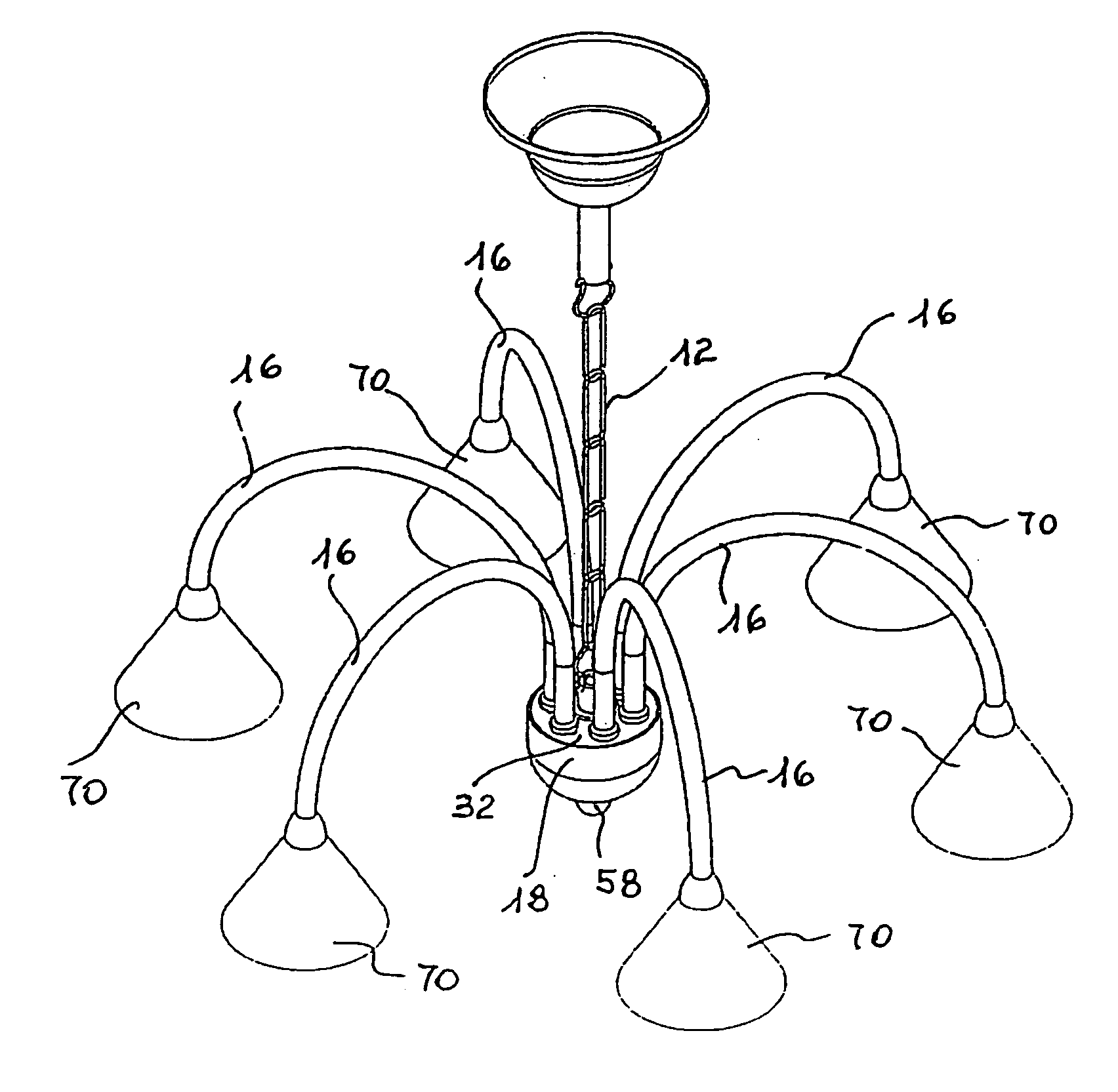
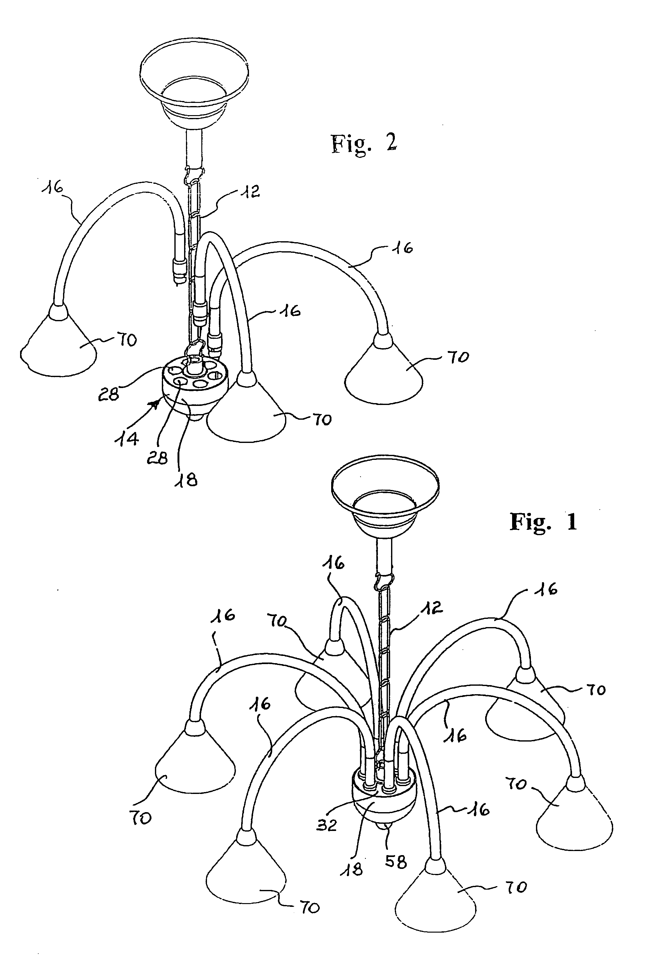
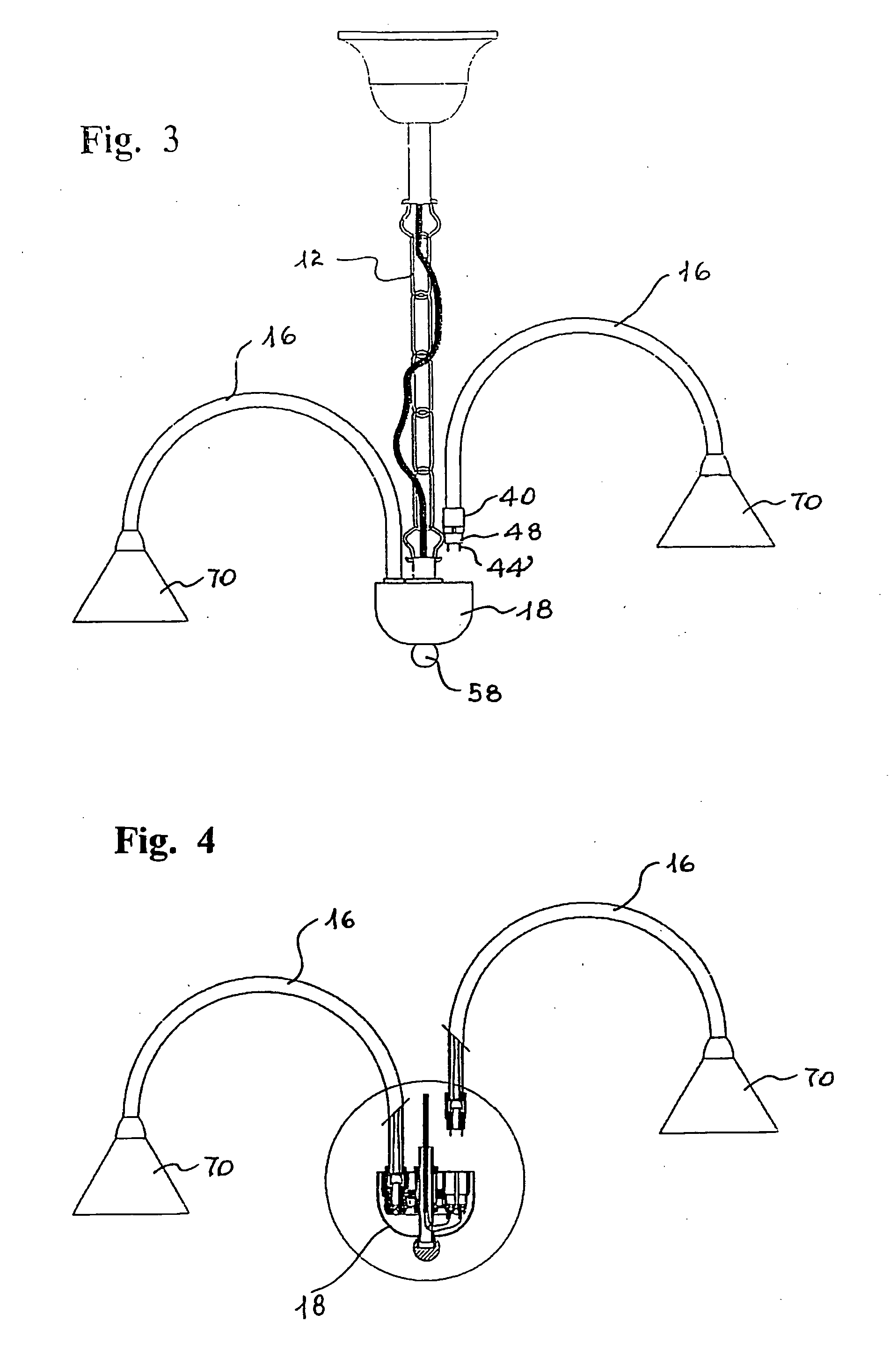
[0026]With reference to the above figures, the modular lighting fixture of the present invention is globally indicated with reference numeral 10 in FIG. 1, which shows a possible embodiment thereof in the form of a chandelier to hang to the ceiling. The lighting fixture 10 comprises a hanging element 12, for example consisting of linked metal rings to be fixed to the ceiling by the top end, a central support 14 fixed to the bottom end of the hanging element 12 and a plurality of arms 16, typically and not critically with arched development, which are fixed to the central support 14.

[0027]The latter comprises a containment body 18 by way of an example shaped as a tray, having a substantially hemispherical profile and open top front, wherein there is seated a plurality of overlapped components, as schematised in FIG. 8. In particular, in the containment body 18 there is inserted a circular plate 20 of insulating material, provided with two concentric seats 22 and 24 suitable for recei...


PUM


Abstract

A modular lighting fixture (10) is provided with a plurality of arms (16) branching off a central support (14) wherein they are inserted pressure-wise starting from the respective bottom ends. The central support comprises a containment body (18) wherein a plate (20) is arranged, with concentric seats (22,24) for as many spiral electrical conductors (22′, 24′) surmounted by a cylindrical plate (26) of insulating material wherein a plurality of through seats (28) with circular plan or wells is peripherally obtained, starting from a plane (30), wherein the bottom ends of arms (16) are inserted, provided with the electrical cables (42) for powering a lighting body connected to the opposite top end of the same arms. The bottom end of the arms is made integral to a sleeve (40) provided, along the base perimeter, with a vertical notch (40′) intended for coupling with a projection (52) protruding from the outer side surface of a cylindrical body (48), whereon the sleeve is fitted pressure-wise.

Description

BACKGROUND OF THE INVENTION[0001]The present invention relates to a modular lighting fixture with improved device for connecting the arms to the respective support.[0002]More in particular, the present invention relates to a modular lighting fixture wherein one or more arms carrying the lighting body or bodies are inserted in the respective support for obtaining both the mechanical connection and the electrical connection by an improved device. The latter is obtained at al end of each arm and fits into a support and containment seat formed on a central body. The term “lighting fixture” used in the present description preferably refers to a ceiling chandelier with arms branching off a central support, made of glass, crystal or other suitable material but the same term may refer to a wall lamp of appliqué with one or more arms, or other types of lamps, for example floor or table lamps.[0003]As known, several types of fixtures used for interior lighting exist. A traditional and widespr...

Claims


Application Information

Patent Timeline
IPC IPC(8): F21S8/06
CPCF21S8/065F21V23/06F21V21/02
Inventor BASSANI, PAOLO
Owner VOLTOLINA FRANCESCO
Why Eureka
Eureka Blog
Learn More