Method and apparatus for transmitting/receiving data in mu-mimo system
- Summary
- Abstract
- Description
- Claims
- Application Information
AI Technical Summary
Benefits of technology
Problems solved by technology
Method used
Image
Examples
embodiment 1
[0034]FIG. 5 is a view illustrating a method for transmitting / receiving data in accordance with an embodiment of the present invention.
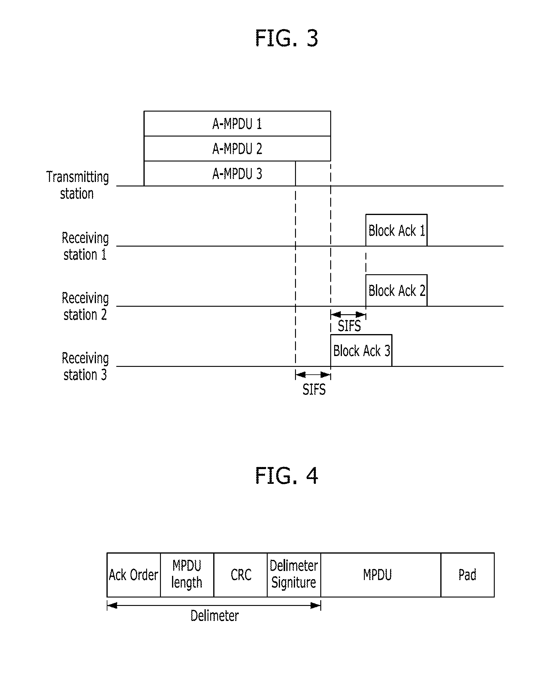
[0035]Referring to FIG. 5, a transmitting station transmits data frames, i.e., first to third A-MPDUs, to the first to third receiving stations through multi channels at the same time. At this time, the order to transmit the block Ack signals to the transmitting station after reception of the data frames is set as follows: the first receiving station, the second receiving station, and the third receiving station (which is represented by Ack order).
[0036]Therefore, the transmitting station generates a plurality of data frames including data to be transmitted to the respective receiving stations and Ack order information, or receives them from the outside. In this embodiment, the Ack order information included in the data frame contains information representing a relative order in which a plurality of receiving stations are to transmit the block Ack si...
embodiment 2
[0039]FIG. 6 is a view illustrating a method for transmitting / receiving data in accordance with another embodiment of the present invention.
[0040]In the embodiment of FIG. 6, data frames transmitted to the respective receiving stations have different lengths, as opposed to the embodiment of FIG. 5. In this case, the respective receiving stations need to complete the reception of the data frames at the same timing so that they transmit their block Ack signals in the Ack order set by the transmitting station.
[0041]Therefore, in the embodiment of FIG. 6, padding bits are inserted so that data frames other than the longest data frame have the same length as the longest data frame. The padding bits may be inserted into either or both of a MAC layer and a PHY layer.
[0042]As illustrated in FIG. 6, the lengths of the respective data frames become equal to one another by the insertion of the padding bits. After the data frames into which the padding bits are inserted are transmitted to the r...
embodiment 3
[0043]FIG. 7 is a view illustrating a method for transmitting / receiving data in accordance with another embodiment of the present invention.
[0044]Like in the embodiment of FIG. 6, data frames in the embodiment of FIG. 7 have different lengths. However, padding bits are not inserted into the data frames, as opposed to the embodiment of FIG. 6. Instead, a transmitting station transmits data frames containing Ack order information that contains information on time for respective receiving stations to transmit block Ack signals. The information on time for the respective receiving stations to transmit the block Ack signals is divided into relative time information and absolute time information.
[0045]For example, the Ack order information may contain information (Ack order=1, 2, 3) representing a relative order in which the receiving stations are to transmit their block Ack signals, which has been described above in the embodiments 1 and 2, and information on relative transmission time (...
PUM
 Abstract
Description
Claims
Application Information
 - R&D
- Intellectual Property
- Life Sciences
- Materials
- Tech Scout
- Unparalleled Data Quality
- Higher Quality Content
- 60% Fewer Hallucinations
Browse by: Latest US Patents, China's latest patents, Technical Efficacy Thesaurus, Application Domain, Technology Topic, Popular Technical Reports.
© 2025 PatSnap. All rights reserved.Legal|Privacy policy|Modern Slavery Act Transparency Statement|Sitemap|About US| Contact US: help@patsnap.com


