Ventilated Roof Apparatus and Method

a technology for ventilating roofs and roofs, applied in ventilation systems, lighting and heating apparatuses, heating types, etc., can solve the problems of inadequate ventilation, air will take the flow path of low resistance, etc., and achieve adequate ventilation, low permeability, and easy adjustment of resistance to air flow.

Inactive Publication Date: 2011-08-18
HENDERSON JOHN C
View PDF47 Cites 21 Cited by
  • Summary
  • Abstract
  • Description
  • Claims
  • Application Information

AI Technical Summary

Benefits of technology

[0028]Nonetheless, resistance to air flow can be readily adjusted by selecting a fabric filter having an appropriate permeability to air; namely, the resistance to air flow per unit area of the fabric. Selecting a fabric filter for the eave vent that has a low permea

Problems solved by technology

If flow paths exist, but if other flow paths present inadequate resistance to air flow, the air will take the flow path of low resistance.
The remainder of the roof

Method used


Image

  • Ventilated Roof Apparatus and Method
  • Ventilated Roof Apparatus and Method
  • Ventilated Roof Apparatus and Method

Examples


Embodiment Construction

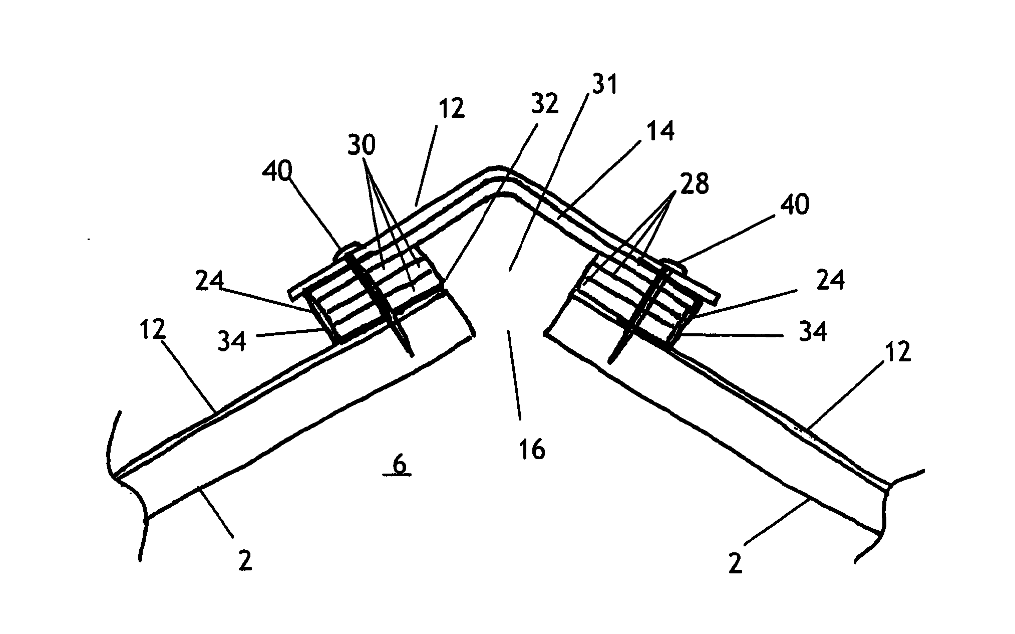
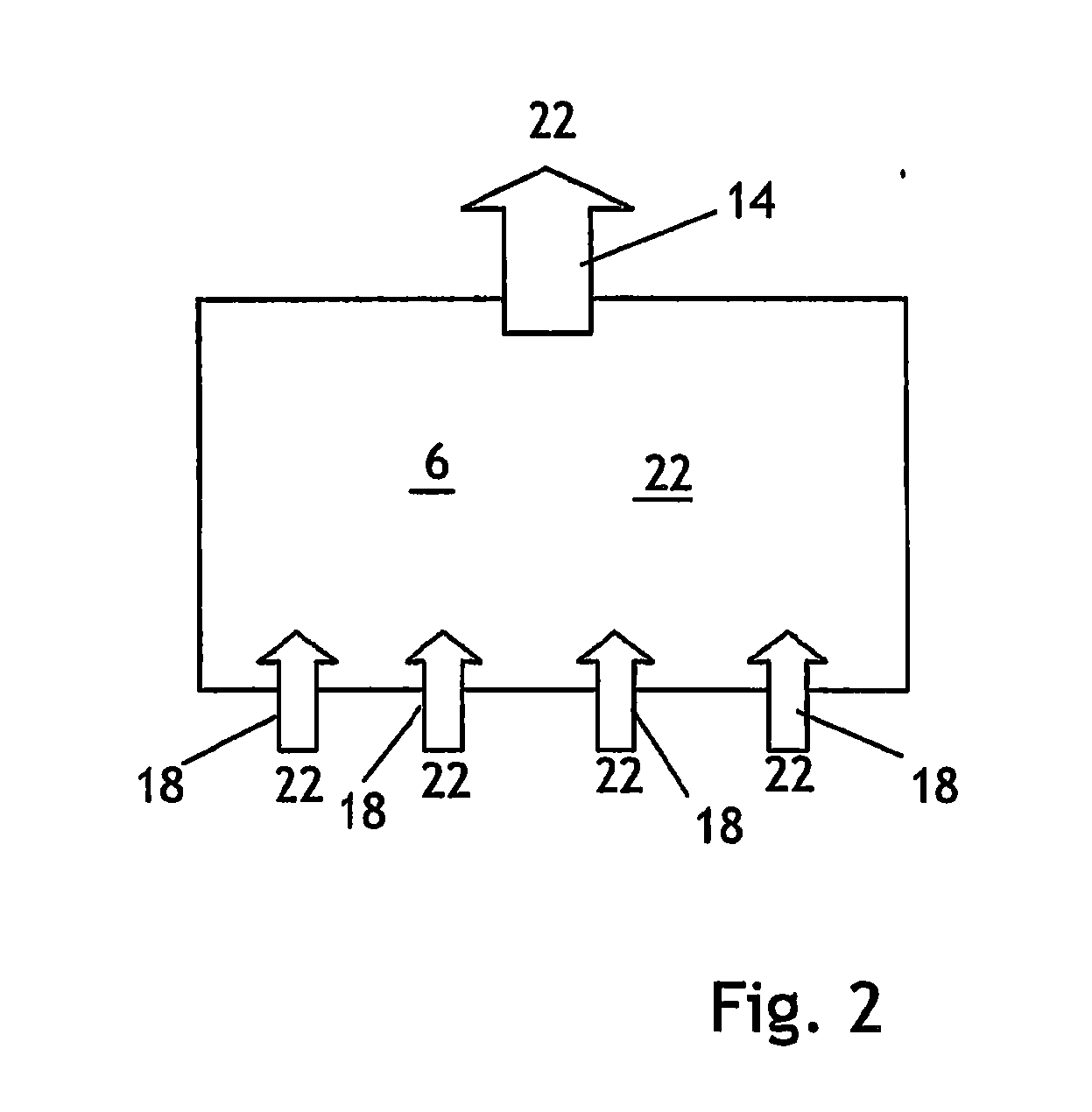
[0041]The invention is an apparatus and method for ventilating an attic space or other area under a roof. As illustrated by FIGS. 1 and 7 through 10, a roof deck 2 covers a structure 4. The structure 4 features an attic space 6 beneath the roof deck 2. As used in this document, the term ‘attic space’ also includes any area under a roof, such as the space between the ceiling and a roof deck 2 of a room having a cathedral ceiling. The roof deck 2 is pitched as illustrated by FIGS. 1 and 7 through 10, meaning that the roof deck 2 defines an adequate angle with the horizontal to allow the use of shingles 12. The roof deck 2 is composed of any suitable planar material, such as plywood or metal sheets. The roof deck 2 defines a ridge 8 at its highest location and an eave 10 at a location lower than the ridge 8.

[0042]As illustrated by FIGS. 1, 3, 4, 9 and 10, the roof includes a ridge vent 14 covering a roof deck ridge vent opening 16 located at the ridge 8 of the roof deck 2. The roof als...


PUM


Abstract

In ventilating a roof, an eave vent and a ridge vent are provided. The eave vent and ridge vent each is equipped with a fabric filter. The fabric filter is not waterproof and is wettable and hence self-cleaning. The permeability to air of the eave vent fabric filter is less than that of the ridge vent fabric filter and the resistance to air flow of the eave vent is greater than that of the ridge vent. The attic space under the roof acts as a manifold, distributing low pressure throughout the attic space.

Description

I. RELATED APPLICATIONS[0001]This application is related to and claims priority from provisional application No. 61 / 337,855 filed Feb. 12, 2010 by the inventor named herein.II. BACKGROUND OF THE INVENTION[0002]A. Field of the Invention[0003]The Invention is an apparatus for ventilating a roof, a roof ventilated using the apparatus of the invention and a method of ventilating a roof using the apparatus.[0004]B. Statement of the Related Art[0005]Moisture trapped in an attic or other space underneath the pitched roof of a structure can damage the roof, can damage the remainder of the structure and can promote growth of mold within the attic. To avoid these effects, the space underneath the roof must be ventilated.[0006]As used in this document, the term ‘attic’ refers to an attic and also refers to any other air space under a roof, such as the space between a ceiling or insulation and a roof deck of a structure equipped with a cathedral ceiling.[0007]During daylight hours, the sun shin...

Claims


Application Information

Patent Timeline
IPC IPC(8): F24F7/02
CPCF24F7/02
Inventor HENDERSON, JOHN C.
Owner HENDERSON JOHN C
Why Eureka
Try Eureka