Energy generating system and control thereof

a technology of energy generation system and energy management, applied in non-electric variable control, process and machine control, instruments, etc., can solve the problems of inability to meet energy demand, new challenges in the management and control of energy generation system, and relatively unreliable power generated from renewable energy sources

Active Publication Date: 2011-08-18
HITACHI ENERGY SWITZERLAND AG
View PDF2 Cites 30 Cited by
  • Summary
  • Abstract
  • Description
  • Claims
  • Application Information

AI Technical Summary

Problems solved by technology

The integration of natural, intermittent, energy sources such as wind power, solar, tidal or wave power, into the power grids of energy generating systems presents a new challenge in the management and control of energy generating systems.
For example, one challenge is the intermittency of their power production which is dependent on meteorological phenomena such as wind speed, solar irradiance, and so forth.
This intermittency results in power generated from renewable energy sources being relatively unreliable compared to traditional energy sources, such as fossil fuels from which energy generation can be actively and accurately dispatched.
If, for example, severely strong winds occur over a wide geographical area for a sustained period of tens of minutes, this mass disconnection of wind turbines would result in the energy output from the energy generation system falling substantially and being unable to meet energy demand.
A change in the weather front over a geographical area can be accompanied by a suddenly weakened wind; this would result in a sudden drop in energy generation, meaning the output from the energy generation system would perhaps not be sufficient to meet user demand.
A sudden wind increase over a wide area could also lead to a rapid increase in the wind power being generated; this in turn could overload transmission lines in the vicinity of the wind generation unit.
Within a few minutes, this could res

Method used


Image

  • Energy generating system and control thereof
  • Energy generating system and control thereof
  • Energy generating system and control thereof

Examples


Embodiment Construction

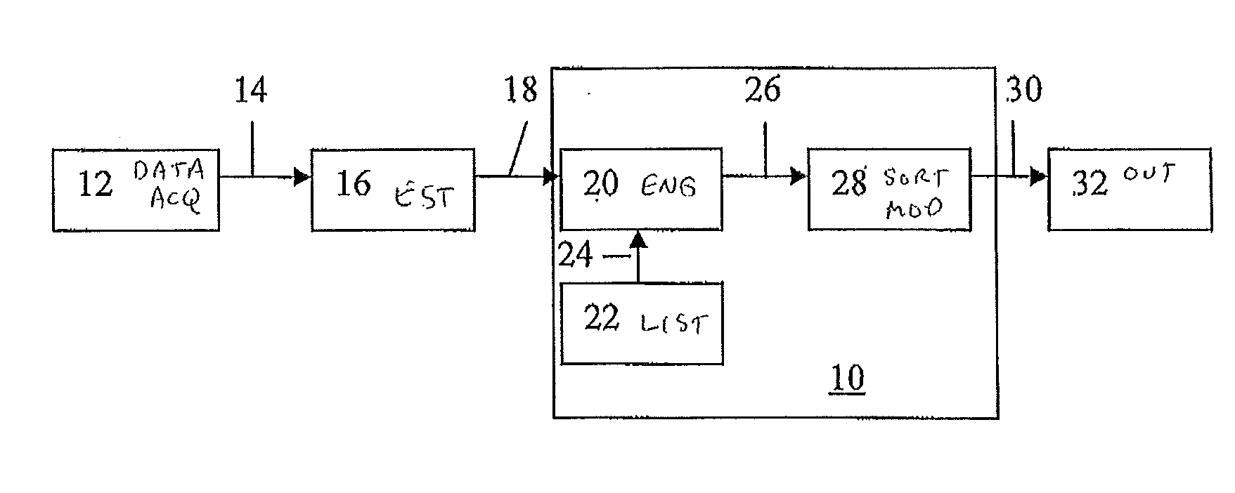
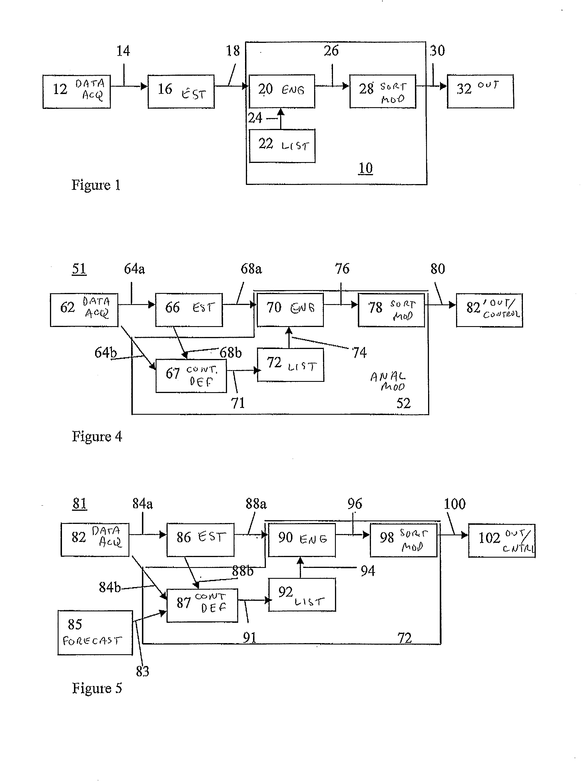
[0026]A system and method are disclosed for controlling an electricity generating system which can provide more secure operation of the electricity generating system in the presence of generation intermittency arising from the use of intermittent energy sources. The electricity generating system can include at least one intermittent energy source generating plant. The method includes calculating operating parameters of the at least one intermittent energy source generating plant; generating intermittent energy source contingency definitions from such operating parameters; analyzing the intermittent energy source contingency definitions to provide contingency analyses; and controlling the electricity generating system in dependence upon such contingency analyses.

[0027]An exemplary alternate method includes generating additional contingency definitions for parts of the generating system other then the at least one intermittent energy source generating plant, and the additional conting...


PUM


Abstract

A system and method of controlling an electricity generating system that includes at least one intermittent energy source generating plant are disclosed. An exemplary method includes calculating actual operating parameters of the at least one intermittent energy source generating plant; calculating forecast operating parameters of the at least one intermittent energy source generating plant; generating intermittent energy source contingency definitions from such actual operating parameters and forecast operating parameters; analysing the intermittent energy source contingency definitions to provide contingency analyses; and controlling the electricity generating system in dependence upon such contingency analyses.

Description

FIELD[0001]An energy generating system and an associated method of control are disclosed, such as an energy system and generating system which includes a wind power generating plant.BACKGROUND INFORMATION[0002]Known energy generating systems have relied on power grids predominantly supplied with energy from fossil fuels and nuclear power. Such energy sources fit comfortably with the need for responsive energy supply and thus the energy generation systems have been reasonably straightforward to both analyze and control. In such energy generating systems, it is known for contingency analysis to be used to facilitate system management. Contingency analysis has been used to analyze the impact of hypothetical disturbance conditions in the power grid of the energy generating system. Such contingency analysis involves analyzing a large set of credible contingencies and, from this analysis, identifying in real time a number of contingencies that could create instability or overload in the p...

Claims


Application Information

Patent Timeline
IPC IPC(8): G06F1/26
CPCG06Q10/04G06Q10/06G06Q50/06Y04S10/54H02J3/386Y02E10/563Y02E10/763H02J3/383Y02P90/82H02J2300/40H02J2300/28H02J2300/24H02J3/381Y02E10/56Y02E10/76Y04S10/50
Inventor LARSSON, MATSTIMBUS, ADRIANFRANKE, CARSTENNACCARINO, JORGE
Owner HITACHI ENERGY SWITZERLAND AG
Why Eureka
Try Eureka