
Absolute displacement detection method and absolute displacement sensor using the method

a detection method and sensor technology, applied in the direction of vibration measurement in solids, acceleration measurement using interia forces, instruments, etc., can solve the problems of vibration problems in conventional homes, multiple dwelling houses, and offices

Active Publication Date: 2011-08-25
SETO KAZUTO +1
View PDF1 Cites 10 Cited by
  • Summary
  • Abstract
  • Description
  • Claims
  • Application Information

AI Technical Summary

Benefits of technology

[0018]According to the present invention, it is possible to provide an absolute displacement detection method which is capable of lowering the natural frequency and enlarging the detectable amplitude without causing a structural defect by feeding back state quantities (displacement, velocity, and acceleration) possessed by the mass body, thereby making it possible to satisfactorily detect the absolute displacement not only in a structure with a high natural frequency and in the case where the structure vibrates with a small amplitude but also in a structure with a low natural frequency and in the case where the structure vibrates with a large amplitude, and making it possible to expand the detection range down to an extremely low frequency and stably detect the absolute displacement without requiring difficult adjustment of the positive feedback of the relative displacement, as well as an absolute displacement sensor using the method.

Problems solved by technology

In recent years, vibration problems have occurred in structures such as offices, enterprise buildings, multiple dwelling houses, and conventional homes due to vibrations attributable to metal working machines, compressors, and the like which are used in factories, business establishments, and construction sites, or due to such as the vibration of the ground and road surfaces attributable to earthquakes or vehicle travel.

Method used


Image

  • Absolute displacement detection method and absolute displacement sensor using the method
  • Absolute displacement detection method and absolute displacement sensor using the method
  • Absolute displacement detection method and absolute displacement sensor using the method

Examples


Embodiment Construction

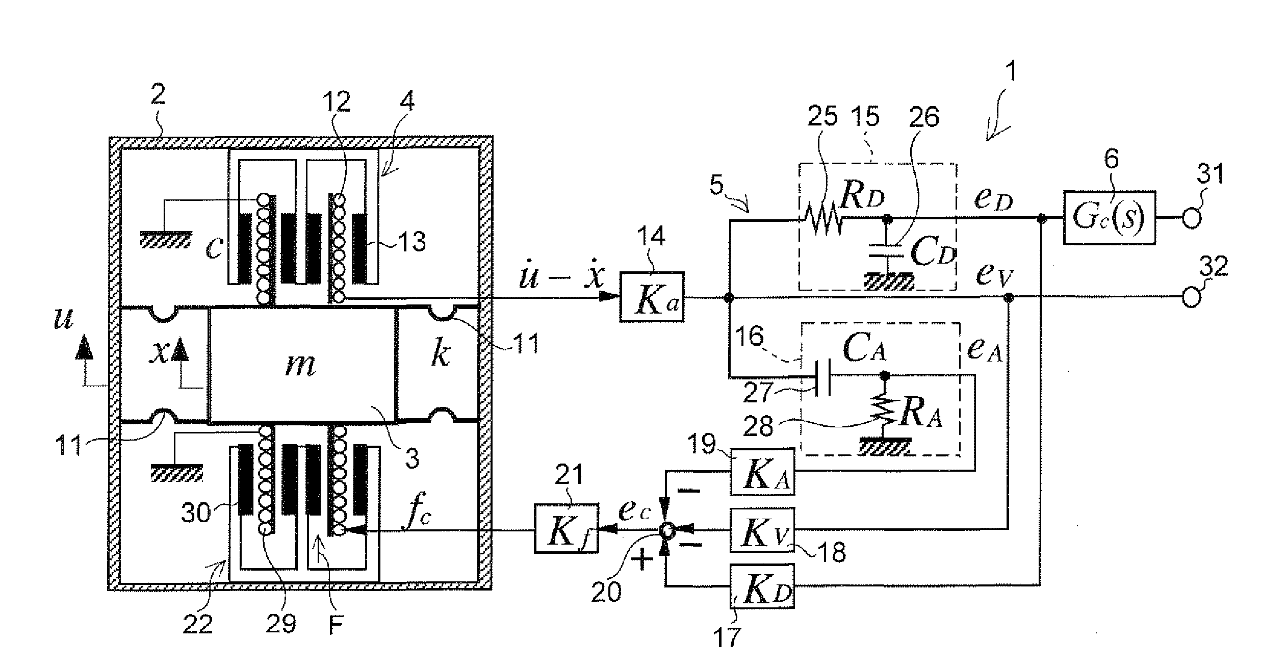
[0024]In FIG. 1, an absolute displacement sensor 1 in accordance with this embodiment is comprised of a sensor housing 2 serving as a detection object; a mass body 3 having a mass m (kg) which is movably supported by the sensor housing 2 with a spring coefficient k (N / m) and a damping coefficient c (Ns / m); a detecting means 4 which electrically detects a relative velocity v (=vu−vx) (m / s) of the sensor housing 2 with respect to the mass body 3 {where vx (m / s) is the absolute velocity of the mass body 3 attributable to the absolute velocity vu (m / s) of the sensor housing 2); a feedback control means 5 which controls the absolute displacement x of the mass body 3 attributable to the absolute displacement u of the sensor housing 2 by positively feeding back a relative displacement (u−x) obtained by integrating the relative velocity v detected by the detecting means 4, by feeding back the detected relative velocity v negatively in this embodiment, and by negatively feeding back a relati...


PUM


Abstract

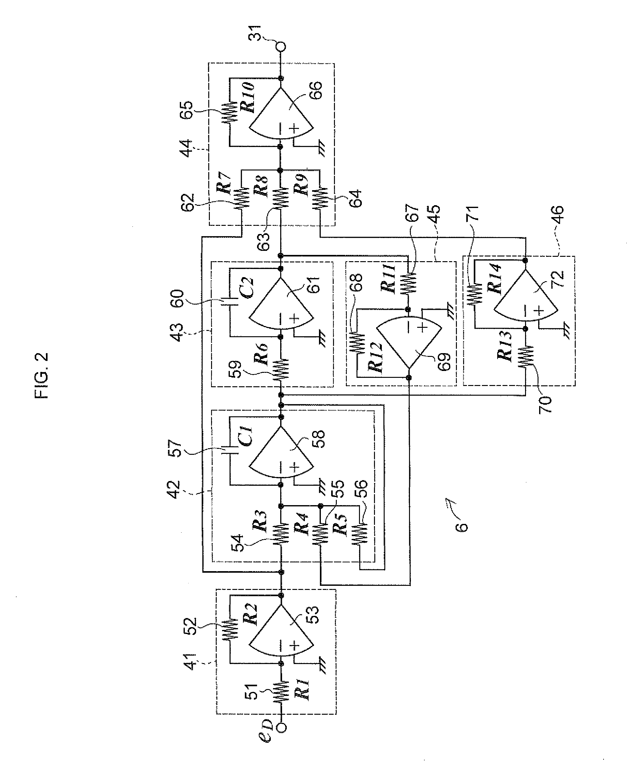
An absolute displacement sensor 1 includes a sensor housing 2 serving as a detection object; a mass body 3 having a mass m which is movably supported by the sensor housing 2 with a spring coefficient k and a damping coefficient c; a detecting means 4 which electrically detects a relative velocity of the sensor housing 2 with respect to the mass body 3; a feedback control means 5 which controls the absolute displacement of the mass body 3 attributable to the absolute displacement of the sensor housing 2 by positively feeding back the relative displacement and by negatively feeding back a relative acceleration obtained by primarily differentiating the relative velocity, respectively; and a phase lag compensation means 6 which performs phase lag compensation with respect to the relative displacement.

Description

TECHNICAL FIELD[0001]The present invention relates to an absolute displacement detection method for detecting the absolute displacement of a vibrating body (detection object) necessary for observation and / or vibration control of such as the vibration of machines attributable to metal working machines, compressors, and the like which are used in factories, business establishments, construction sites, etc., the vibration of buildings and machinery due to such as the vibration of the ground and road surfaces attributable to earthquakes, vehicle travel, and the like, and the vibration of skyscraper buildings due to vortex-induced vibrations caused by wind or due to earthquakes, as well as an absolute displacement sensor using that method.BACKGROUND ART[0002][Patent Document 1] JP-A-2003-130628[0003]In recent years, vibration problems have occurred in structures such as offices, enterprise buildings, multiple dwelling houses, and conventional homes due to vibrations attributable to metal...

Claims


Application Information

Patent Timeline
Patent Type & Authority Applications(United States)
IPC IPC(8): G01H11/00G01H1/00
CPCG01P3/52G01V1/181G01P15/16G01P15/11
Inventor SETO, KAZUTO
Owner SETO KAZUTO
Learn More