Scanning electron microscope
a scanning electron microscope and scanning technology, applied in closed circuit television systems, electric discharge tubes, television systems, etc., can solve problems such as adverse effects on observed images, and achieve the effect of reducing vibration
- Summary
- Abstract
- Description
- Claims
- Application Information
AI Technical Summary
Benefits of technology
Problems solved by technology
Method used
Image
Examples
first embodiment
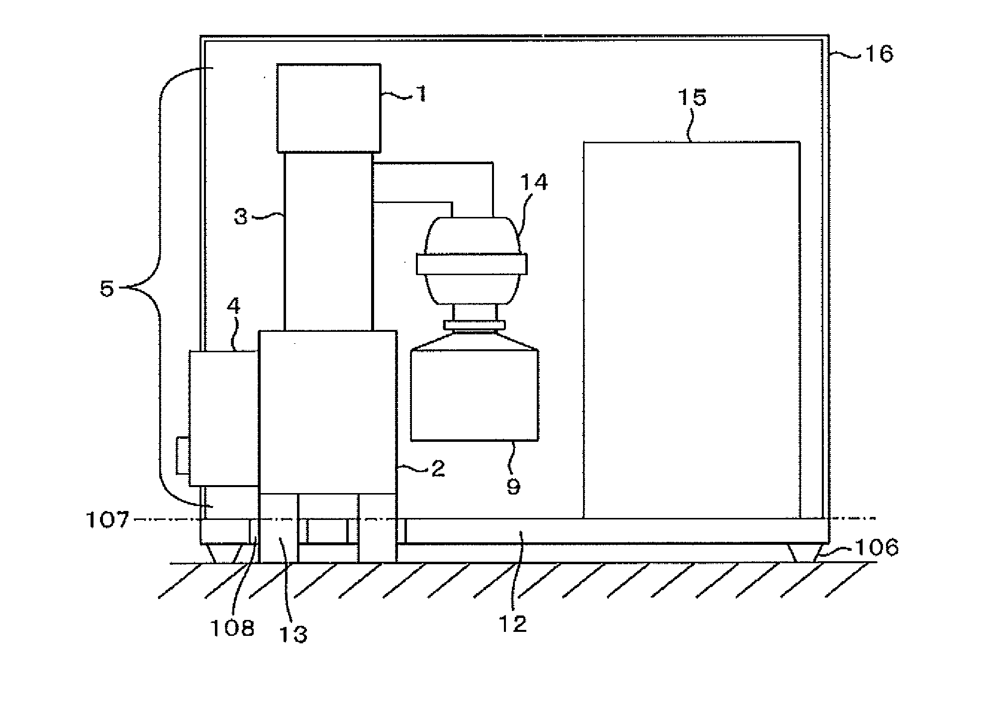
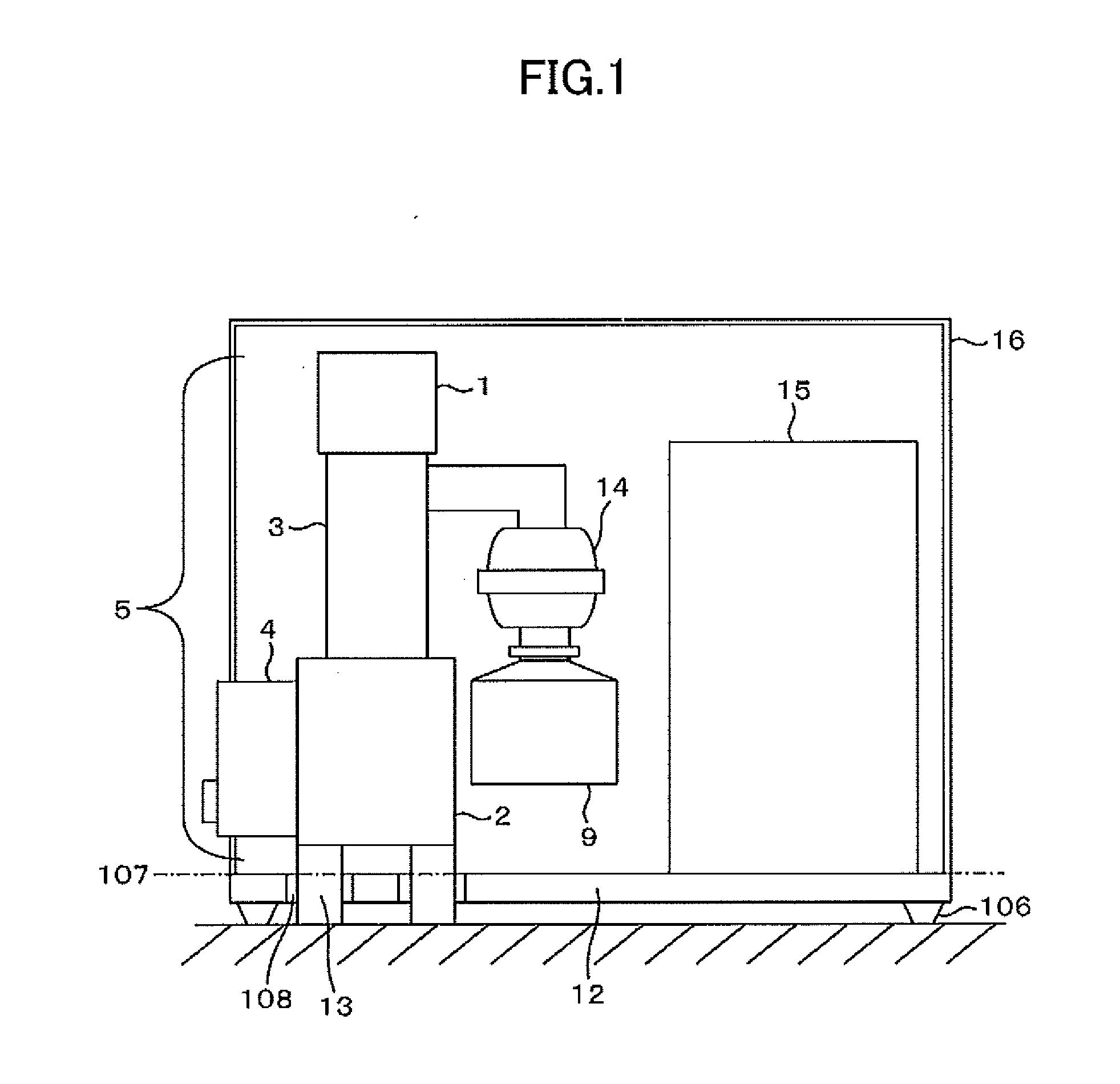
[0022]An explanation is given on a structure of a desktop type scanning electron microscope in which a damper is in direct contact with a floor surface through an opening hole bored through the bottom plate.
[0023]Firstly a structure of an electron scanning microscope is explained with reference to FIG. 4. A main scanning electron microscope unit for the present embodiment is constituted by such devices as an electron beam gun 1, a lens unit 3 as a sample chamber 2. As is not shown in FIG. 4, a sample stage is installed inside the sample chamber 2. When the apparatus is being used, an inside of the apparatus is vacuumed to a vacuum level higher than or equal to a predetermined vacuum level. When a high voltage is applied to an electron source 17, an electron beam 18 is emitted. Since the emitted electron beam 18 undergoes a convergence action from a potential of a wehnelt electrode 19, the emitted electron beam 18 propagates along on a curved trajectory and a first crossover 21 is fo...
second embodiment
[0029]In the case of the structure shown in FIG. 1, the vibration reduction property is improved over the conventional structure because the control unit 15 to be a vibration source is separated from the bottom plate 12. However, since the main scanning electron microscope unit 5 is not connected with the bottom plate 12 at all, the main scanning electron microscope unit 5 can not follow the other parts of the total apparatus that are moving and forced to be dragged when the total apparatus is being moved. In case there is some impact applied to the apparatus, the main scanning electron microscope unit 5 as well as the damper could leap up onto the bottom plate 12. In the present embodiment, a following mechanism to have the main scanning electron microscope unit follow the bottom plate moving is additionally attached to get rid of the above mentioned risk. Hereinafter a structure inclusive of this following mechanism is to be explained.
[0030]FIG. 5 is an elevation view for a scanni...
third embodiment
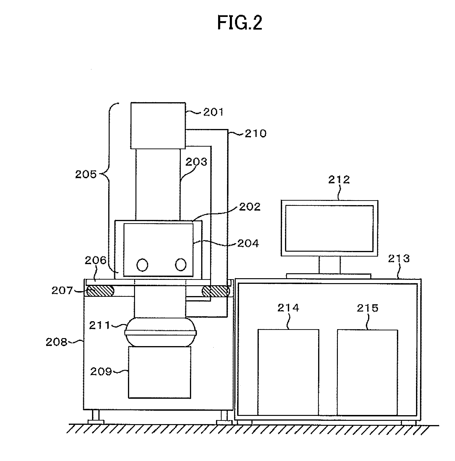
[0036]In the first embodiment an explanation is given on the structure of the desktop type scanning electron microscope which has a damper in direct contact with the floor surface. However there is problem with the main scanning electron microscope unit following the bottom plate if the damper is disposed simply on the apparatus installation plane. Therefore the following mechanism as is used for the second embodiment is needed. The present embodiment has a structure with which the damper is allowed to be made longer than the conventional structure while there is not such a problem with the following as for the first embodiment.
[0037]Firstly the vibration reduction structure of the present embodiment is to be explained. The internal structure of the electron optical column is the same as the first embodiment and its explanation is skipped.
[0038]FIG. 6 shows a cross section of the structure of a desktop type scanning electron microscope of the present embodiment. A main scanning elec...
PUM
 Abstract
Description
Claims
Application Information
 - R&D
- Intellectual Property
- Life Sciences
- Materials
- Tech Scout
- Unparalleled Data Quality
- Higher Quality Content
- 60% Fewer Hallucinations
Browse by: Latest US Patents, China's latest patents, Technical Efficacy Thesaurus, Application Domain, Technology Topic, Popular Technical Reports.
© 2025 PatSnap. All rights reserved.Legal|Privacy policy|Modern Slavery Act Transparency Statement|Sitemap|About US| Contact US: help@patsnap.com


