

Method and apparatus for electrical control of heat transfer
- Summary
- Abstract
- Description
- Claims
- Application Information
AI Technical Summary
Benefits of technology
Problems solved by technology
Method used
Image

Examples
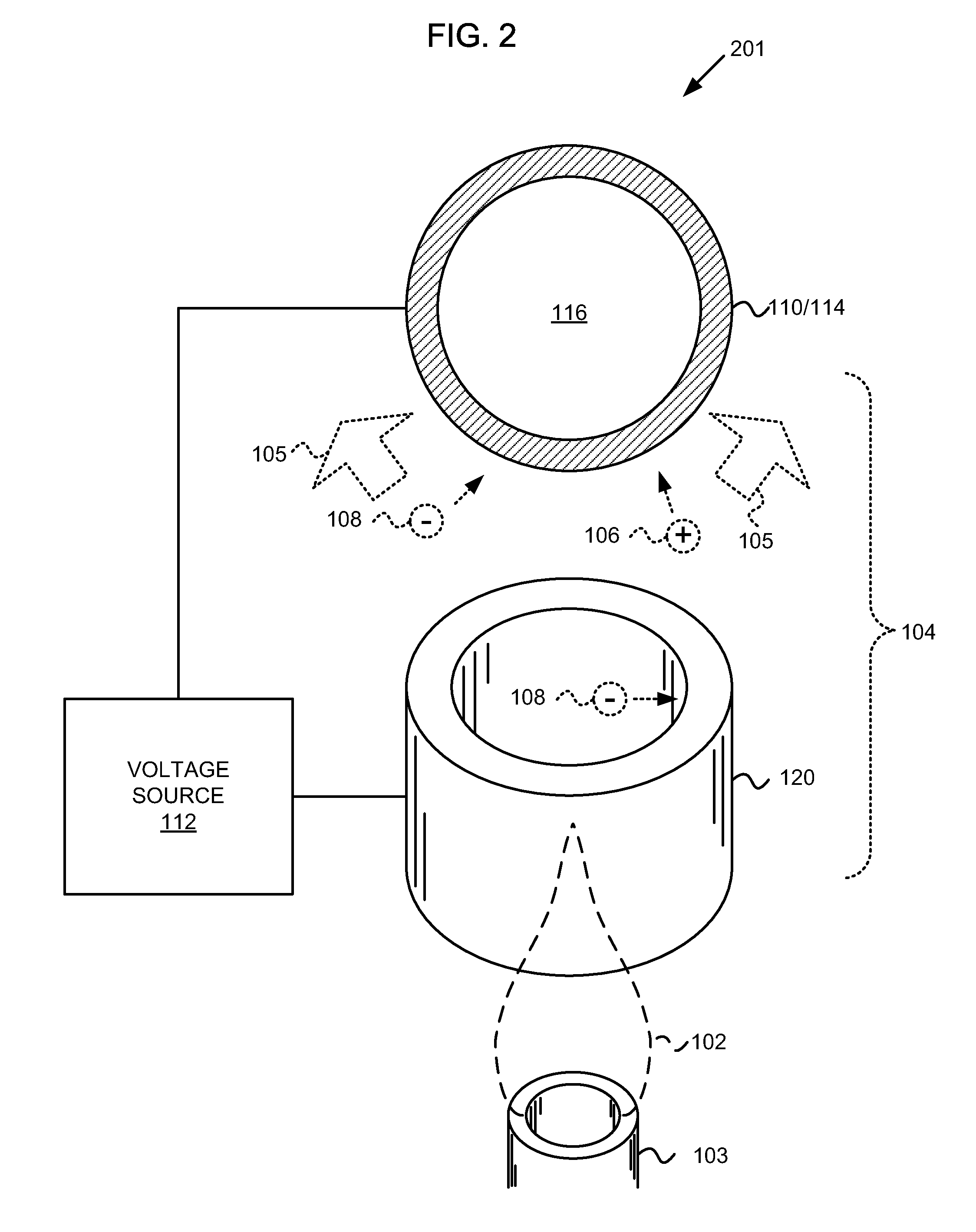
embodiment 201
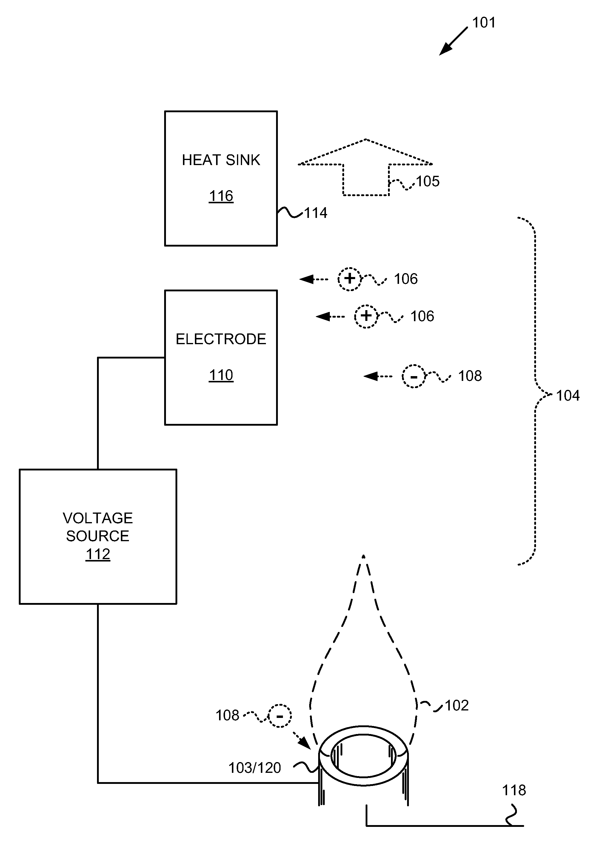
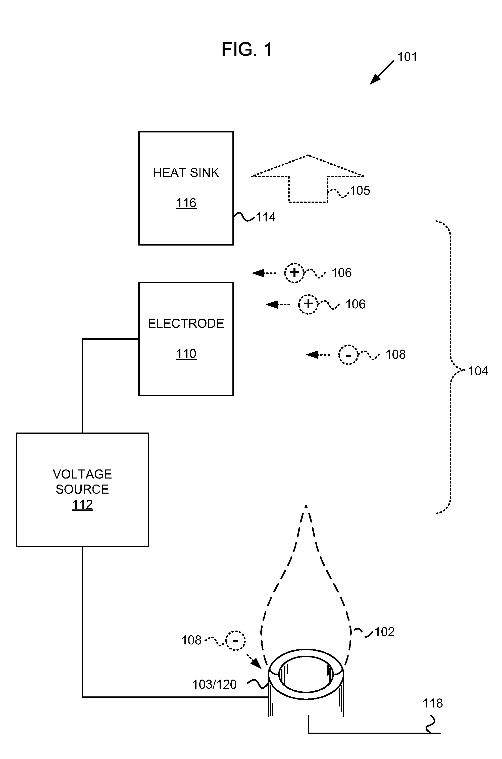
[0033]According to the embodiment 201, the at least one second electrode 120 includes an electrode positioned at a location nearer the burner assembly 103 than the distance between the burner assembly 103 and the heat transfer surface 114. For example, the at least one second electrode 120 may be positioned and driven to sweep electrons 108 out of the flow of the heated gas 104. The modulation of the at least one second electrode 120 may include providing an alternating voltage. The voltage to which the voltage driver 112 drives the second electrode 120 may attract the electrons 108 to the surface of the second electrode 120. The electrons 108 may combine with a positively charged conductor including the at least one second electrode 120 and thus be removed from the heated gas stream 104.
[0034]While the open cylindrical or toric shape of the second electrode 120 represents one embodiment, alternative shapes may be appropriate for alternative embodiments.
[0035]In the embodiment 201, ...
embodiment 301
[0037]According to some embodiments, it may be desirable to provide an apparatus 301 including an integrated electrode 110 and heat transfer surface 114 wherein the electrode 110 is electrically isolated from the heat transfer surface 114. The embodiment 301 may include a thermally conductive wall extending from the heat transfer surface 114. The thermally conductive wall may extend to an opposite surface 302 or may extend to an extension of the heat transfer surface 114 (such as in a cylindrical heat sink 116) or may extend to an opposite surface that is discontinuous from the heat transfer surface 114, but which is adiabatic.
[0038]An electrical insulator 304 may be disposed over at least a portion of the thermally conductive wall extending from the heat transfer surface 114. The first electrode 110 may include an electrically conductive layer disposed over at least a portion of the electrical insulator 304.
[0039]Various electrical insulators 302 may be used. According to embodimen...
PUM
 Abstract
Description
Claims
Application Information