
Power tool and torque adjustment method for the same

a technology of torque adjustment and power tool, which is applied in the field of power tools, can solve the problems of reducing the service life of the power tool, affecting the efficiency of work, and the inefficiency of the conventional power tool, so as to prevent damage to the driver and enhance the efficiency at work

Inactive Publication Date: 2011-08-25
MOBILETRON ELECTRONICS
View PDF6 Cites 20 Cited by
  • Summary
  • Abstract
  • Description
  • Claims
  • Application Information

AI Technical Summary

Benefits of technology

[0006]It is one objective of the present invention to provide a power tool, which can have a means to automatically adjust an optimal torque to a user-selected driver, thereby enhancing efficiency at work and preventing damage to the driver.
[0008]When detecting the to-be-detected member, the detecting member will transmits a signal to the torque adjustment unit so as to apply a suitable torque to the driver, thereby preventing damage to the driver.
[0009]It is another objective of the present invention to provide a torque adjustment method of a power tool, which can prevent damage to the driver when the torque setting is wrong.
[0010]To achieve this objective of the present invention, the torque adjustment method comprises steps of assembling a driver with an output end of a housing of the power tool, and detecting whether the driver is equipped with a to-be-detected member by means of a detecting member mounted in the output end of the housing of the power tool, and employing the detecting member to transmit a signal to a torque adjustment unit disposed in the housing of the power tool when detecting the driver is equipped with the to-be-detected member such that the torque adjustment unit can automatically adjust a torque applied torque to reach a predetermined value, thereby preventing damage to the driver.

Problems solved by technology

However, the operator is easy to set a wrong torque value of the torque adjustment unit by his negligence, such as the torque adjustment unit is set to a high torque value during the operation of the impact bit, or the torque adjustment unit is set to a low torque value after the installation of the drill bit.
In the situation of improper operation, the conventional power tool has drawbacks of inefficiency at work, damage to the driver, and reduction in the service life of the power tool.

Method used


Image

  • Power tool and torque adjustment method for the same
  • Power tool and torque adjustment method for the same
  • Power tool and torque adjustment method for the same

Examples


Embodiment Construction

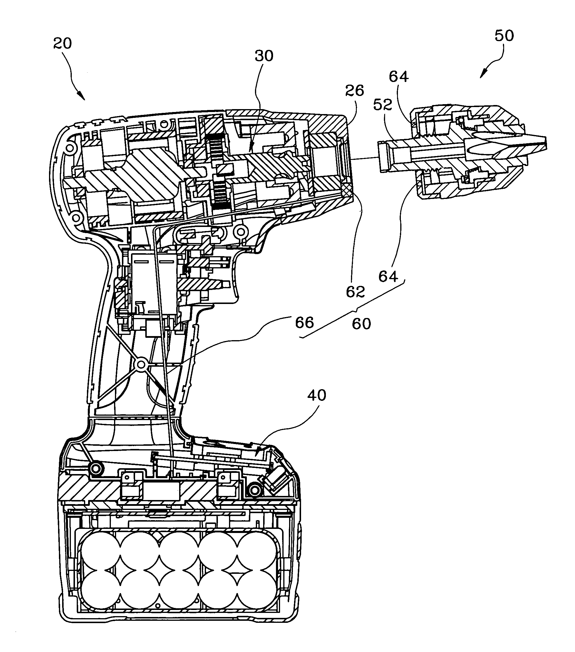
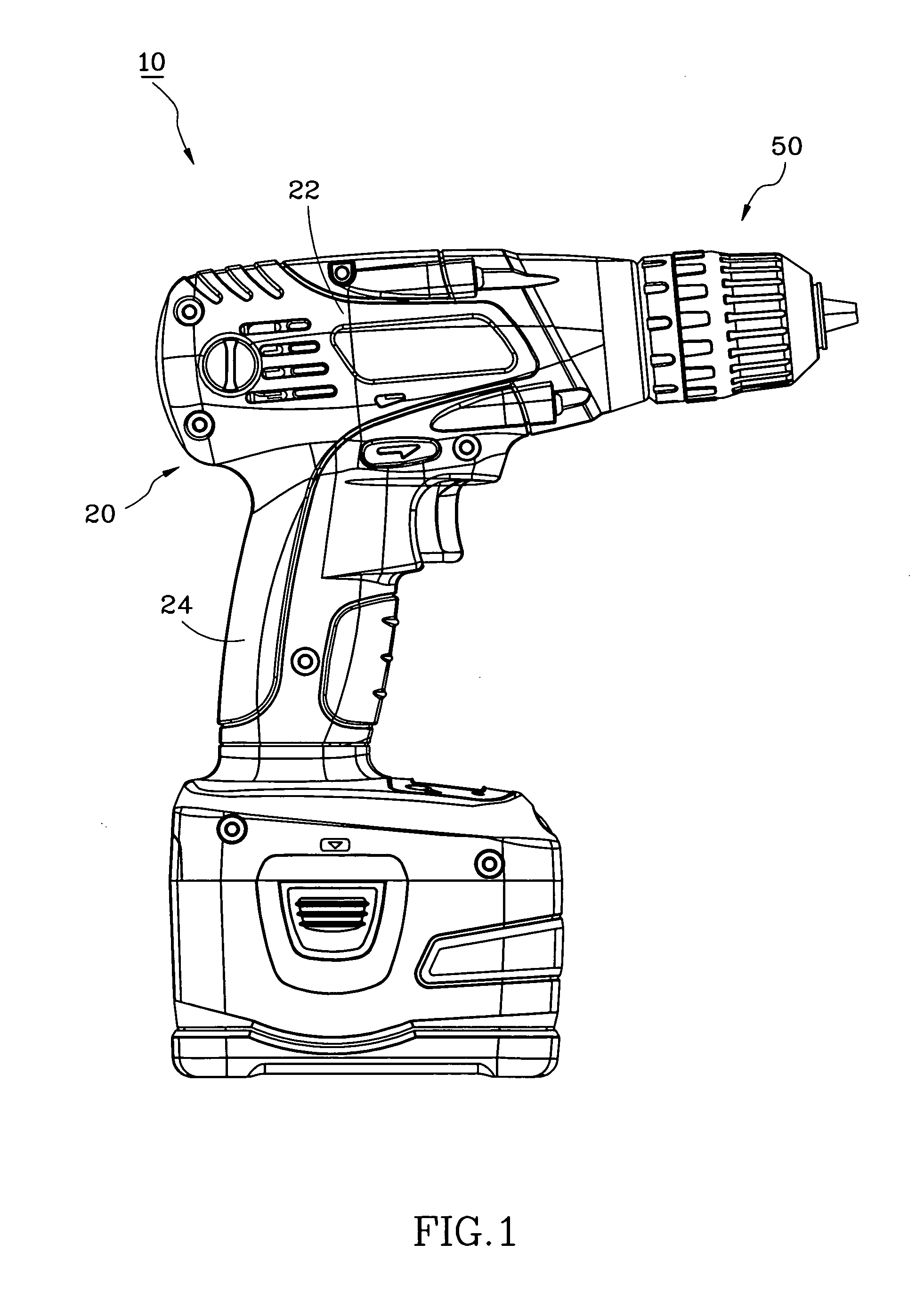
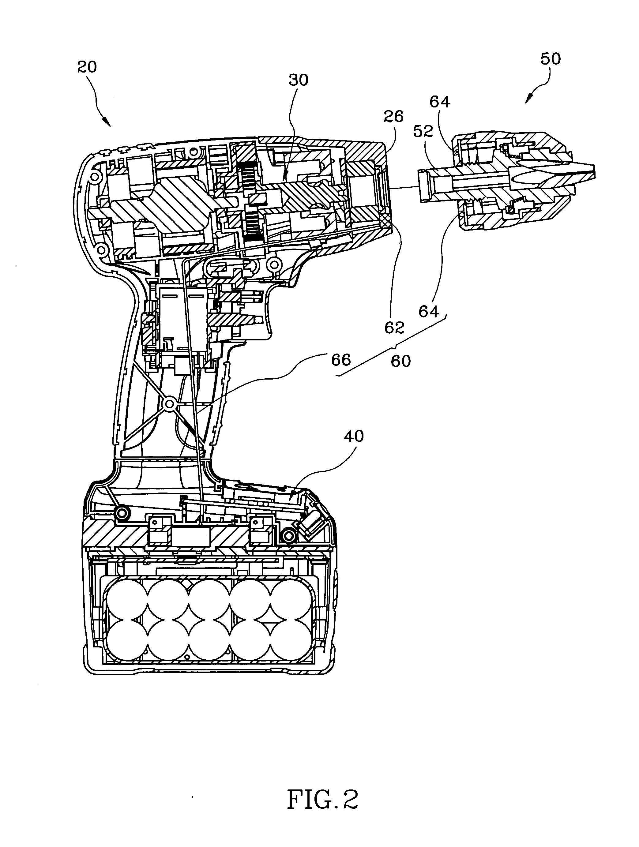
[0017]Referring to FIGS. 1 to 2, a power tool 10 in accordance with a preferred embodiment of the present invention comprises a housing 20, a driving unit 30, a torque adjustment unit 40, a driver 50, and a sensor assembly 60.

[0018]The housing 20 has a driving portion 22, a grip portion 24 extending downwards from the driving portion 22, and an output end 26 formed at the front end of the driving portion 22.

[0019]The driving unit 30 is installed in the driving portion 22 of the housing 20.

[0020]The torque adjustment unit 40 is disposed in the bottom of the grip portion 24 of the housing 20 for adjusting a torque produced by the driving unit 30.

[0021]The driver 50 has a shaft 52 inserted into the output end 26 of the housing 20 for connection with the driving unit 30 such that the driver 50 can be rotated by the actuation of the driving unit 30.

[0022]The sensor assembly 60 has a detecting member 62 embodied as a magnetic sensor, and two to-be-detected members 64 each embodied as a ma...


PUM


Abstract

A power tool includes a detecting member mounted in an output end of a housing, and a to-be-detected member mounted in a driver. When the driver is assembled with the output end of the housing, the detecting member will detect the to-be-detected member and transmit a signal to a torque adjustment unit disposed in the housing so as to enable the torque adjustment unit to automatically adjust the torque applied to the driver to reach a predetermined value, thereby preventing damage to the driver.

Description

BACKGROUND OF THE INVENTION[0001]1. Field of the Invention[0002]The present invention relates generally to a power tool, and more specifically to a power tool that has a means for automatically adjusting the torque applied to a driver, and a torque adjustment method for the power tool.[0003]2. Description of the Related Art[0004]A conventional power tool is used to drill holes in a workpiece or secure screws on a workpiece through a driver actuated by a motor. The power tool can apply different torques to different types of drivers according to different operating requirements. For example, a drill bit requires a high torque to operate, and an impact bit needs a low torque to work. Therefore, the power tool is usually equipped with a torque adjustment unit for adjusting an output torque applied to the driver and allowing an operator to set the torque valve in light of the type of the driver.[0005]However, the operator is easy to set a wrong torque value of the torque adjustment unit...

Claims


Application Information

Patent Timeline
Patent Type & Authority Applications(United States)
IPC IPC(8): B23Q5/10B25B23/147
CPCB25B21/00B25F5/001B25B23/14B25F3/00
Inventor TSAI, KIM Y.C.TENG, CHENG-IYEH, CHIA-CHANG
Owner MOBILETRON ELECTRONICS
Learn More