Fuel tank and evaporated fuel processing device including the fuel tank

a technology of processing device and fuel tank, which is applied in the direction of liquid fuel feeder, machine/engine, transportation and packaging, etc., can solve the problem of fuel in the fuel tank becoming more rapidly evaporated

Inactive Publication Date: 2011-08-25
TOYOTA JIDOSHA KK
View PDF10 Cites 19 Cited by
  • Summary
  • Abstract
  • Description
  • Claims
  • Application Information

AI Technical Summary

Benefits of technology

[0009]The present invention provides a fuel tank that prevents the forming of the

Problems solved by technology

However, when a fuel temperature in the fuel tank rises along with a temperature

Method used


Image

  • Fuel tank and evaporated fuel processing device including the fuel tank
  • Fuel tank and evaporated fuel processing device including the fuel tank
  • Fuel tank and evaporated fuel processing device including the fuel tank

Examples


Embodiment Construction

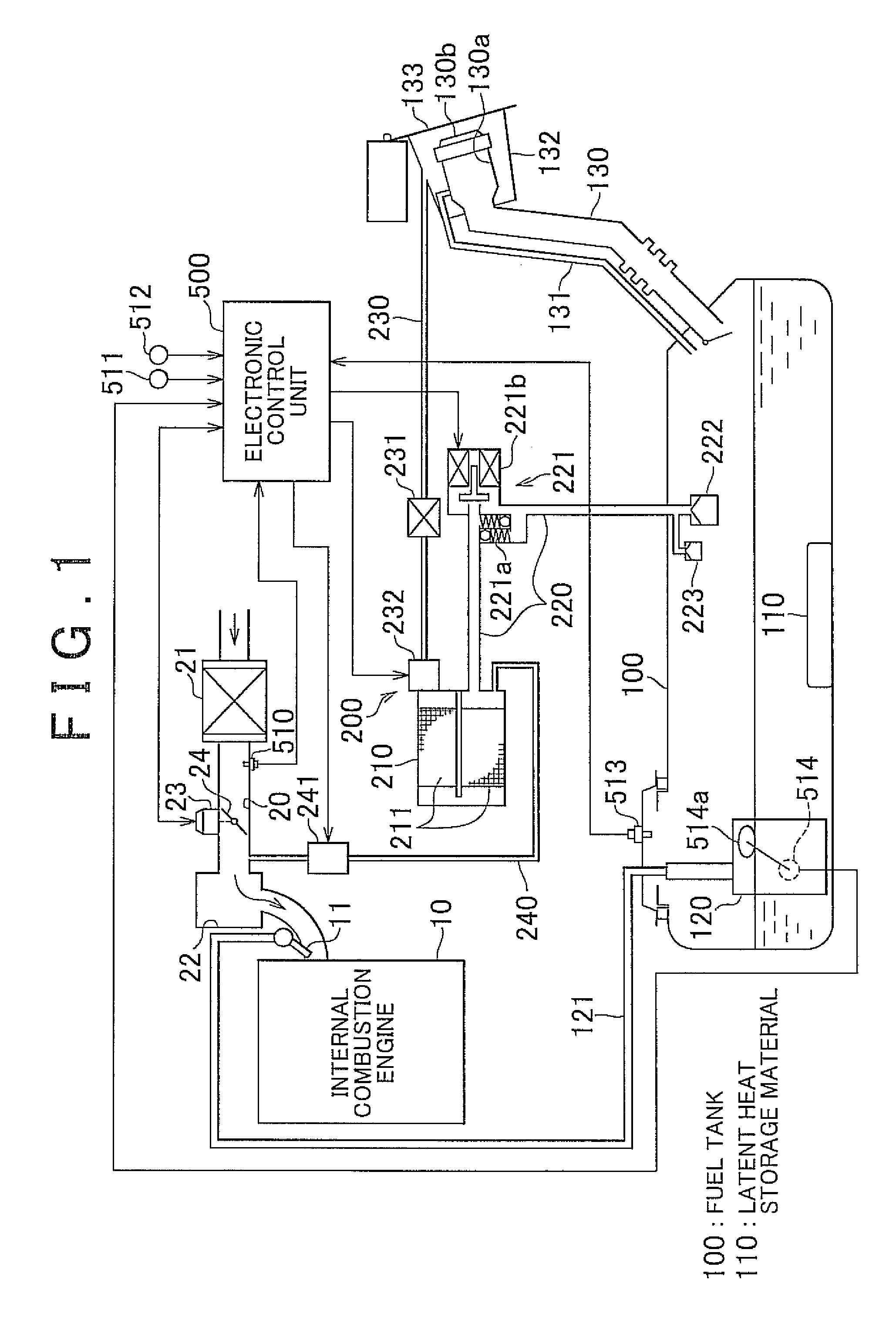
[0035]Hereinafter, with reference to FIG. 1 and FIG. 2, an embodiment will be described, in which the fuel tank and the evaporated fuel processing device that includes the fuel tank according to the present invention are embodied as the fuel tank and the evaporated fuel processing device installed in a vehicle. FIG. 1 shows a schematic construction of an evaporated fuel processing device 200 according to the present embodiment.

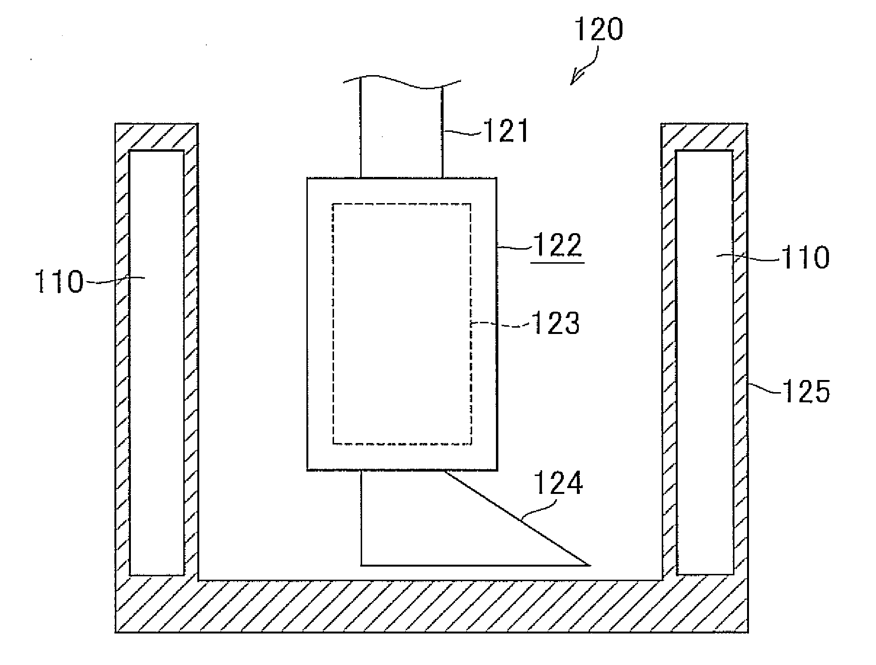
[0036]As shown in a lower portion of FIG. 1, a fuel tank 100 is provided with a pump module 120 that pumps up the fuel stored in the fuel tank 100. A pressure sensor 513 that detects a pressure in the fuel tank 100 is disposed on the upper portion of the fuel tank 100.

[0037]The pump module 120 is connected through a fuel supply 121 to a fuel injection valve 11 of an internal combustion engine 10. Accordingly, the fuel, which is pumped up from the fuel tank 100 by the pump module 120, is supplied through the fuel supply pipe 121 to the fuel injection valve 11. ...


PUM


Abstract

A latent heat storage material, in which a phase-change substance that changes its phase from a solid to a liquid when the temperature of stored fuel rises, is disposed in a fuel tank of the present invention.

Description

CROSS-REFERENCE TO RELATED APPLICATIONS[0001]This application claims priority to Japanese Patent Application No. 2010-037538 filed on Feb. 23, 2010, which is incorporated herein by reference in its entirety including the specification, drawings and abstract.BACKGROUND OF THE INVENTION[0002]1. Field of the Invention[0003]The present invention relates to a fuel tank that stores a liquid fuel and further to an evaporated fuel processing device that includes the fuel tank.[0004]2. Description of the Related Art[0005]In the fuel tank that stores liquid fuel, the fuel is evaporated from its surface and a fuel vapor is formed in the fuel tank. Japanese Patent Application Publication No. 2004-308483 (JP-A-2004-308483) discloses an evaporated fuel processing device in which a fuel vapor formed in the fuel tank is introduced to an intake passage of an internal combustion engine to be burned therein while the engine is running. In such evaporated fuel processing device, the fuel vapor formed i...

Claims


Application Information

Patent Timeline
IPC IPC(8): B65D88/74F02M37/20
CPCF02M25/089F02M37/20F02M37/0082
Inventor OGAWA, YOSHIHIDE
Owner TOYOTA JIDOSHA KK
Why Eureka
Try Eureka