Ultrasonic motor
a technology of ultrasonic motor and ultrasonic vibrator, which is applied in piezoelectric/electrostrictive/magnetostrictive devices, piezoelectric/electrostriction/magnetostriction machines, electrical apparatus, etc., can solve the problems of inability to achieve the downsizing of ultrasonic vibrators and complicated overall structure of conventional vibrators, and achieves simplified overall structure and less wirings
- Summary
- Abstract
- Description
- Claims
- Application Information
AI Technical Summary
Benefits of technology
Problems solved by technology
Method used
Image

Examples
first embodiment
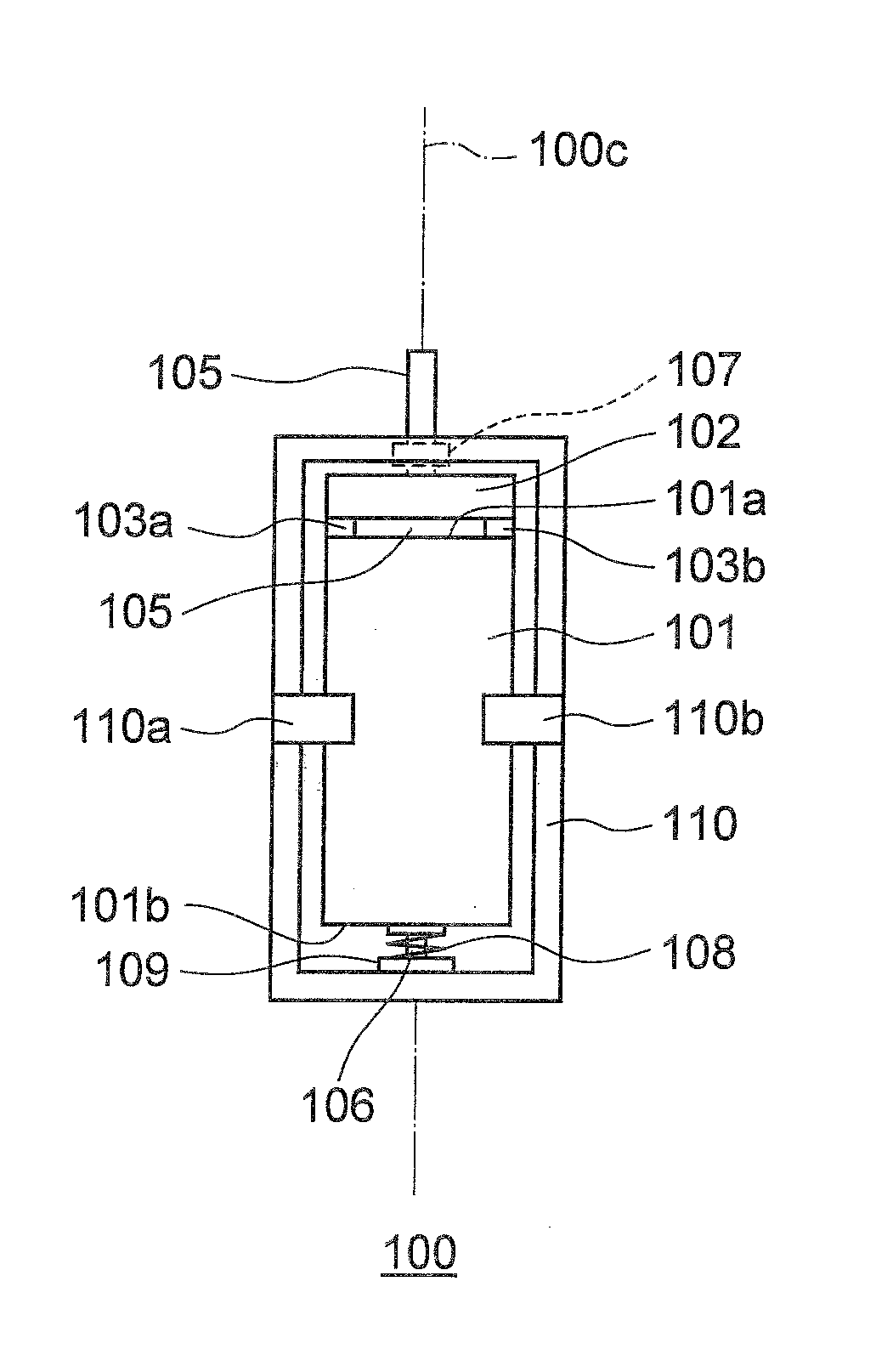
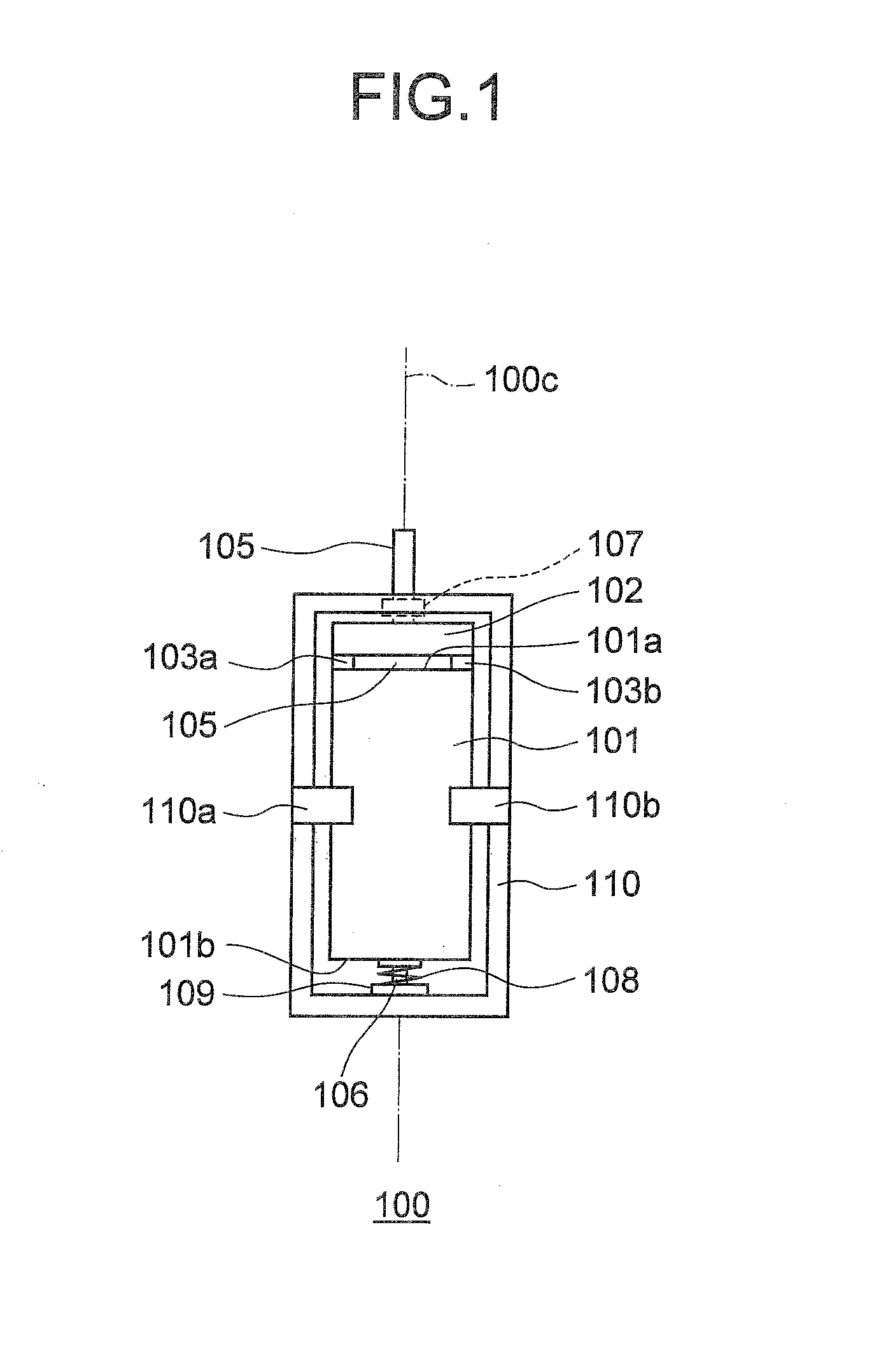
[0038]FIG. 1 is a front view of a structure of an ultrasonic motor 100 according to a first embodiment of the present invention.
[0039]The ultrasonic motor 100 includes a vibrator 101 and a rotor 102. The vibrator 101 is a piezoelectric element of a substantially rectangular parallelepiped shape having a dimension ratio of a rectangle in a cross-section orthogonal to its central axis 100c (rotation axis). Supporting members 110a and 110b that extend from a holder 110 arranged so as to enclose the vibrator 101 are fixed near a node of the vibrator 101 (piezoelectric element).
[0040]The rotor 102 is substantially disk-shaped. A bottom surface of the rotor 102 is in contact with friction contact members 103a and 103b that are arranged on an elliptical vibration generating surface 101a that is on an upper surface of the vibrator 101. A shaft 105 extends from a center of an upper surface of the rotor 102 along the central axis 100c. The shaft 105 is coupled to a bearing 107 held by the hol...
second embodiment
[0090]In an ultrasonic motor according to a second embodiment, the vibration detecting electrode layers in a vibrator are formed at different positions from that of the ultrasonic motor according to the first embodiment. Rest of the structure is similar to that of the ultrasonic motor according to the first embodiment and detailed explanation of the structure other than the vibrator is omitted.
[0091]Structures of a vibrator 201 and a multilayered piezoelectric element 220 are explained below with reference to FIGS. 9 to 12E. FIG. 9 is an exploded perspective view of the structure of the multilayered piezoelectric element 220 according to the second embodiment. FIG. 10A is a plan view of a structure of a second piezoelectric sheet 240, FIG. 10B is a plan view of a structure of a third piezoelectric sheet 250, FIG. 10C is a plan view of a structure of a fourth piezoelectric sheet 260, and FIG. 10D is a plan view of a structure of a fifth piezoelectric sheet 270. FIG. 11 is a perspecti...
third embodiment
[0113]An ultrasonic motor according to the third embodiment differs from the ultrasonic motor 100 according to the first embodiment in that among external electrodes connected to driving electrode layers and vibration detecting electrode layers, all the external electrodes that need to be wired when the ultrasonic motor is being driven are formed on a front face of a multilayered piezoelectric element and the external electrodes other than these are formed on a rear face of the multilayered piezoelectric element. Rest of the structure is the same as that of the ultrasonic motor 100 according to the first embodiment and detailed explanation of the structure other than the vibrator is omitted.
[0114]Structures of a vibrator 301 and a multilayered piezoelectric element 320 are explained below with reference to FIGS. 14 to 17B. FIG. 14 is an exploded perspective view of the structure of the multilayered piezoelectric element 320 according to the third embodiment. FIG. 15A is a plan view ...
PUM
 Abstract
Description
Claims
Application Information
 - R&D
- Intellectual Property
- Life Sciences
- Materials
- Tech Scout
- Unparalleled Data Quality
- Higher Quality Content
- 60% Fewer Hallucinations
Browse by: Latest US Patents, China's latest patents, Technical Efficacy Thesaurus, Application Domain, Technology Topic, Popular Technical Reports.
© 2025 PatSnap. All rights reserved.Legal|Privacy policy|Modern Slavery Act Transparency Statement|Sitemap|About US| Contact US: help@patsnap.com