Eureka AIR delivers breakthrough ideas for toughest innovation challenges, trusted by R&D personnel around the world.

Flexible fibre optic deformation sensor system and method

Inactive Publication Date: 2011-08-25
UNIVERSITY OF NEW BRUNSWICK
View PDF5 Cites 9 Cited by
  • Summary
  • Abstract
  • Description
  • Claims
  • Application Information

AI Technical Summary

Benefits of technology

[0019]According to another embodiment, this invention relates to a method for measuring displacement by providing a cable having at least two lengths of optical fibre, wherein the optical fibre experiences a Brillouin effect in response to strain and temperature, introducing a first light into the first length of optical fibre such that the Brillouin effect in the optical fibre affects the first light to produce a second light, receiving the second light from the second length of optical fibr

Problems solved by technology

However, this raises a problem when large engineering projects require the sensing to be done over several kilometers because numerous point sensors are required.
Distributed optical fibre sensing is not well known and has been slow to be accepted into conservative large engineering projects where long sensors would be advantageous.
Traditionally, optical fibre connections were thought to be costly and troublesome.
However, the cost of using fibre optics has fallen rapidly.
This is problematic since the Brillouin frequency is dependent on both local strain and temperature variables.
Calculations of Brillouin frequency using such a set-up are inaccurate, however, since they are made with the assumption that the temperature is the same for both fibres; however, in reality, it is common for the temperatures to differ.
In addition, even when the temperatures of the fibres are the same, thermal expansion of the host material will cause additional temperature-dependant strain that is not compensated for by the temperature-only fibre.
Although this increases the likelihood that the fibres experience the same temperature conditions, thermal expansion can cause additional strain in the strain-measuring fibre that is not compensated for by the temperature-measuring fibre.
In addition, these devices place the strain-sensing fibre along the neutral axis of the substrate and therefore cannot measure the curvature or displacement of the substrate itself.

Method used


Image

  • Flexible fibre optic deformation sensor system and method
  • Flexible fibre optic deformation sensor system and method
  • Flexible fibre optic deformation sensor system and method

Examples


example # 1

Example #1

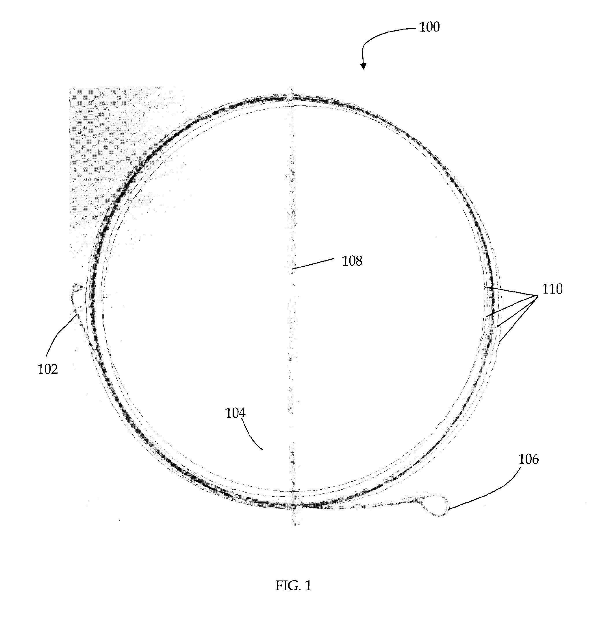
[0044]A 46.15 cm radius circle was made from wrapping a 12 m steel tape onto itself. Approximately four concentric circles were wrapped one on top of the other to form the circle.

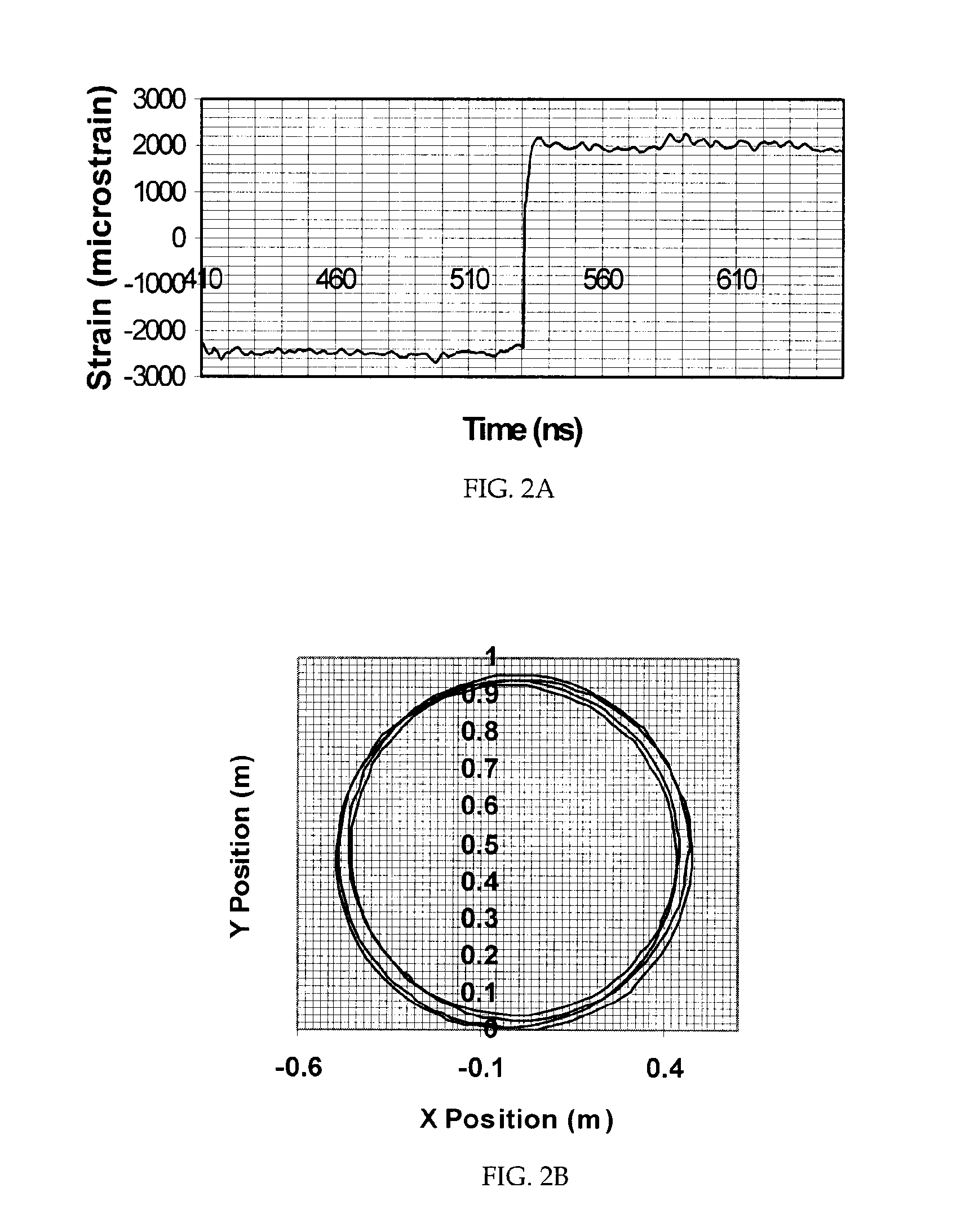
[0045]Data was gathered on the circle configuration. FIG. 2A shows the strain distribution data collected over the length of the circularly wrapped tape.

[0046]As shown in FIG. 2A, a region of compression exists from 410 ns to 530 ns (located between 41.87 m and 54.13 m along the sensing fibre), and a region of tension exists from 530 ns to 650 ns (between 54.13 m and 66.38 m). This is exactly what is expected from a circular shape, since one side of the tape will be in tension, and the opposite in compression.

[0047]FIG. 2B shows the result of the processed strain data captured from the tape. The radius of the circle was determined with a measuring tape to be 46.15 cm; the average radius of curvature as measured with the sensor was 46.065 cm. This yields a 0.184% error or 0.170 cm. The standard dev...

example # 2

Example #2

[0048]An incandescent lamp was used to heat a small portion of the tape, changing the local temperature and introducing some axial strain due to the thermal expansion of the steel. The room temperature during the experiment was 21.8° C. The temperature of the heated section varied between 50.6° C. and 53.2° C. during the data acquisition. FIG. 3A shows the difference between the tape's strain with the lamp placed on it and at room temperature. As in Example #1, the top fibre strain occurs between 410 ns and 530 ns, and the bottom fibre strain occurs between 530 ns and 650 ns. Since a shift in temperature has the same effect on the fibre Brillouin frequency as a shift in strain, periodic peaks of ‘strain’ were expected.

[0049]Periodic spikes are shown in the graph of FIG. 3A. The spikes occur, approximately, every 30 ns, or 300 cm. Just below 530 ns to 540 ns, there is a distortion representing the turn around at the end of the fibre. Given the radius of the circle is 46.15 ...


PUM


Abstract

A cable for distributed fibre optic sensing comprising a flexible tape, an optical fibre suitable for Brillouin scattering measurement forming at least two lengths, and at least one free end of at least one length being connectable to a reading unit, wherein at least a section of the longitudinal length of the flexible tape is situated between at least a section of the two lengths such that the two lengths are in close proximity such that a temperature gradient between the two lengths is minimized, and wherein the section of the tape and the section of lengths can flex together.

Description

FIELD[0001]The present invention relates to measuring deformation in general and measuring deformation using Brillouin scattering in particular.BACKGROUND[0002]Deformation sensing can be achieved by placing point sensors across a certain range. However, this raises a problem when large engineering projects require the sensing to be done over several kilometers because numerous point sensors are required.[0003]Conventionally, a distributed sensor is a device with a linear measurement basis, which is sensitive to a measure and at any of its points. Distributed optical fibre sensing is not well known and has been slow to be accepted into conservative large engineering projects where long sensors would be advantageous. The optical fibre is sensitive over its entire length. A single distributed optical fibre sensor can replace thousands of discrete point sensors. Traditionally, optical fibre connections were thought to be costly and troublesome. However, the cost of using fibre optics ha...

Claims


Application Information

Patent Timeline
IPC IPC(8): G01B11/16G01J3/00G01K11/32
CPCG01B11/18G01K11/32G01D5/35303G01D5/35358
Inventor BROWN, ANTHONYCOLPITTS, BRUCE
Owner UNIVERSITY OF NEW BRUNSWICK
Why Eureka
Eureka Blog
Learn More