
Image forming apparatus and control method thereof

a technology of image forming and printing material, which is applied in the direction of electrographic process apparatus, optics, instruments, etc., can solve the problems of unnatural image for the user who views the color image, unnatural image formation, and difficulty in adjusting the gloss level of an image formed on a printing material to the desired gloss level, so as to prevent regions with different gloss levels and uniform gloss level

Inactive Publication Date: 2011-08-25
CANON KK
View PDF13 Cites 7 Cited by
  • Summary
  • Abstract
  • Description
  • Claims
  • Application Information

AI Technical Summary

Benefits of technology

[0009]The present invention has been made in consideration of the above problems, and provides an image forming apparatus which can prevent regions having different gloss levels from being generated on an image to be formed, and can attain a uniform gloss level on the entire image upon forming an image using a transparent toner.
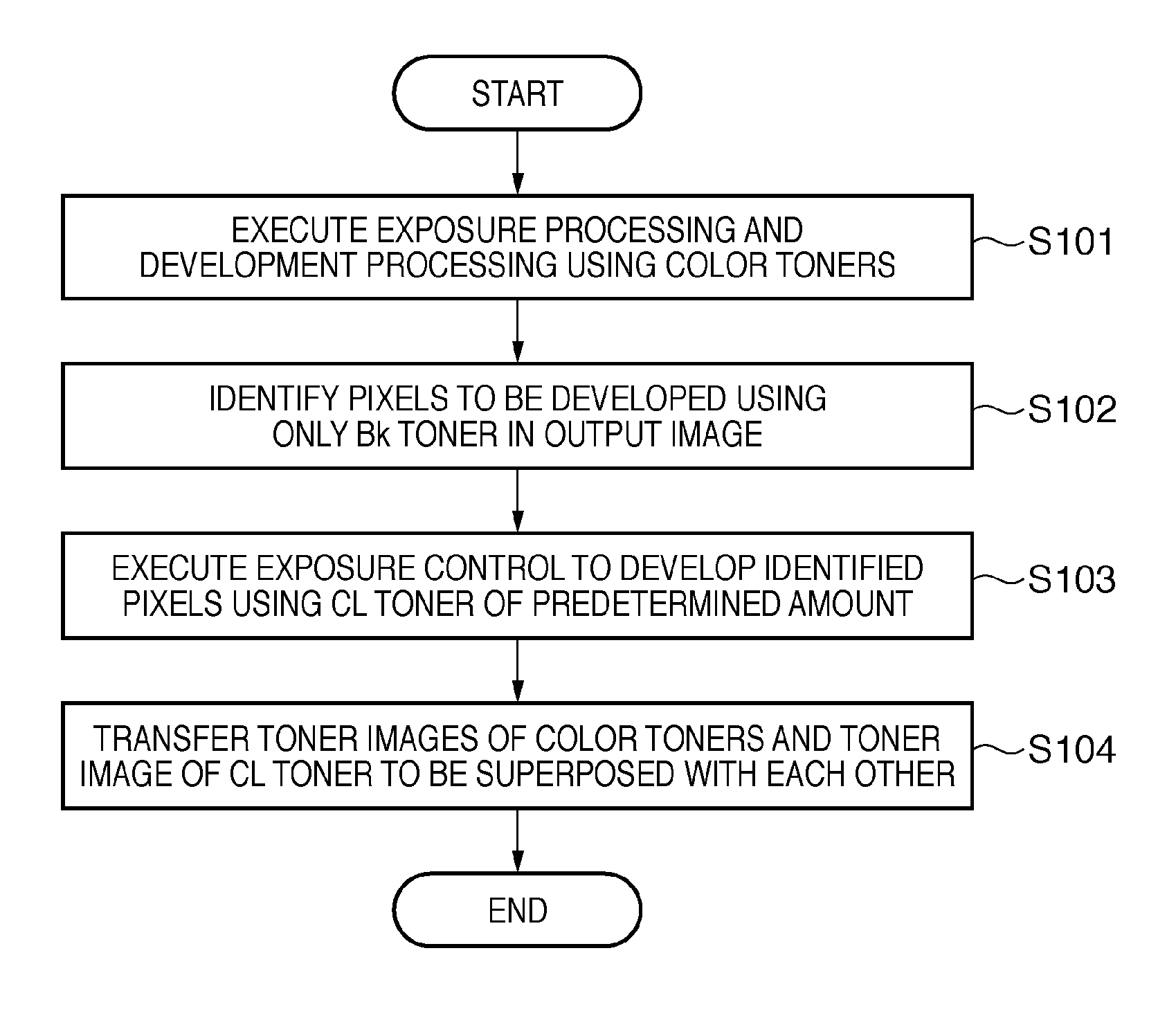
[0011]Another aspect of the present invention provides a control method of an image forming apparatus which comprises an image carrier, an exposure unit that exposes the image carrier in accordance with an image signal of an image to be formed on a printing material to form an electrostatic latent image on the image carrier, a plurality of first developing units that respectively develop the electrostatic latent images using different colored developing materials to form developing material images on the image carrier, and a second developing unit that develops the electrostatic latent image using a transparent developing material, which is used to gloss an image to be formed on the printing material using the colored developing materials, to form a developing material image on the image carrier, the method comprising: identifying, from the image signal, pixels to be developed using only a black developing material of the plurality of colored developing materials; controlling an exposure amount of the exposure unit so as to develop the identified pixels by the second developing unit using the transparent developing material in an amount required to reduce a gloss level difference between the pixels to be developed using only the black developing material and pixels to be developed using the colored developing materials other than the black developing material; and transferring a plurality of developing material images formed by the plurality of first developing units and a developing material image formed by the second developing unit from the image carrier to the printing material to be superposed with each other.
[0012]According to the present invention, the image forming apparatus which can prevent regions having different gloss levels from being generated on an image to be formed, and can attain a uniform gloss level on the entire image upon forming an image using a transparent toner can be provided.

Problems solved by technology

However, the aforementioned related arts suffer the following problems.
For example, gloss levels on a color image formed on a printing material are often uneven depending on the types and amounts of toners to be used.
As a result, an unnatural image for the user who views the color image is unwantedly formed.
The image forming apparatuses disclosed in Japanese Patent Laid-Open Nos. 9-200551, 6-222646, and 2004-70010 above cannot cope with such problem, and it is difficult to adjust a gloss level of an image formed on a printing material to a desired gloss level.

Method used


Image

  • Image forming apparatus and control method thereof
  • Image forming apparatus and control method thereof
  • Image forming apparatus and control method thereof

Examples


first embodiment

Arrangement of Copying Machine 100

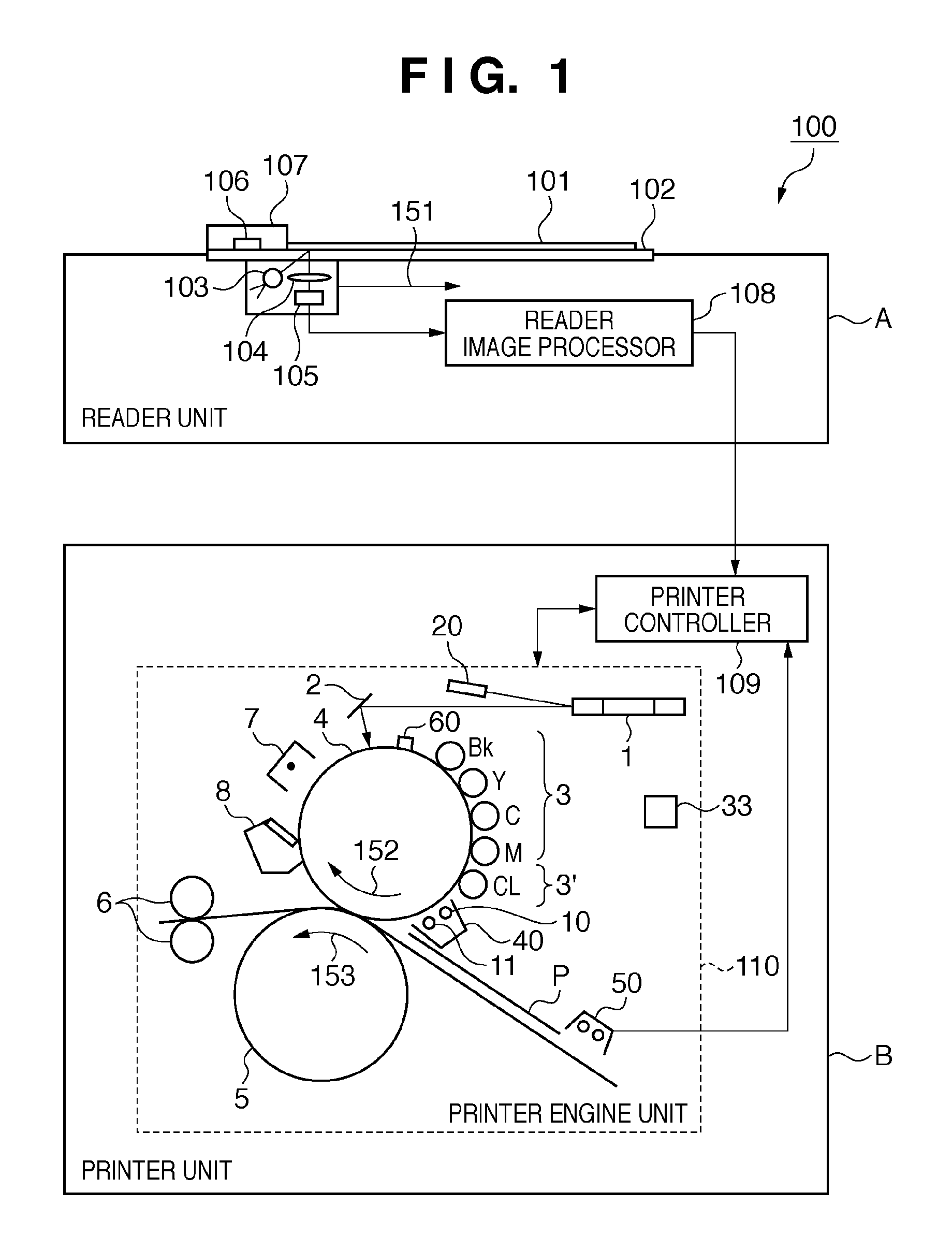
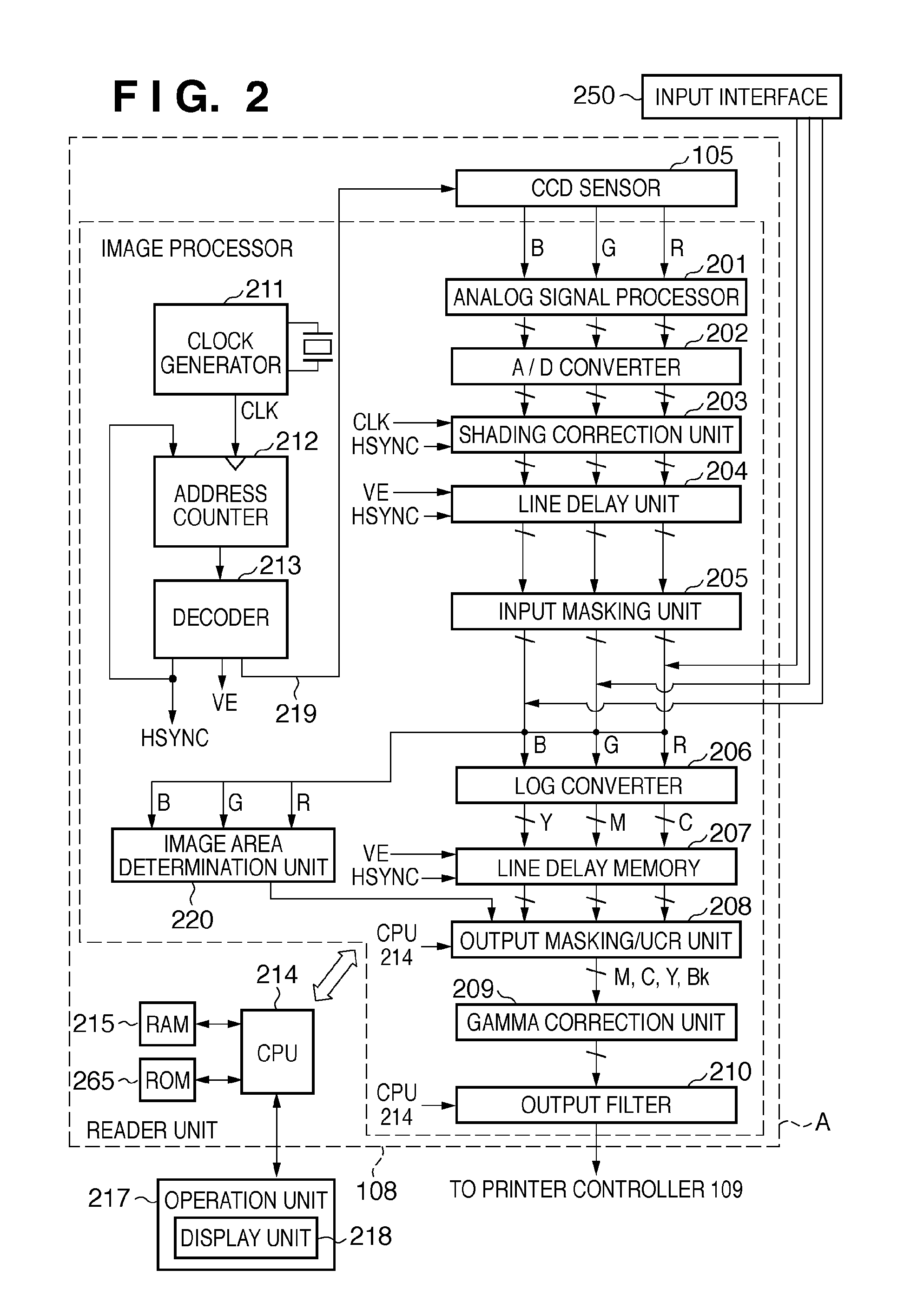
[0030]The first embodiment of the present invention will be described below with reference to FIGS. 1 to 7. This embodiment will exemplify a full-color digital copying machine (to be simply referred to as “copying machine” hereinafter) of an electrophotography method to which the present invention is applied. A copying machine 100 shown in FIG. 1 is an example of an image forming apparatus according to the present invention. The copying machine 100 roughly includes an image reading unit (reader unit A) which reads an image on a document, and converts the read image into image data, and an image forming unit (printer unit B) which forms (prints) an image on a printing material using image data. The copying machine 100 realizes a copy function of printing, on a printing material by the printer unit B, an image read by the reader unit A. Note that the copying machine 100 may have a printer function of printing image data, which is input from an externa...

second embodiment

[0069]The first embodiment assumes the case in which an amount of a transparent toner used in a developer 3′ is fixedly set to form an image using the transparent toner. However, printing materials themselves to be used in image formation often have different gloss levels depending on their types. In this case, the amount of the transparent toner required to attain a uniform gloss level on an output image onto a printing material changes. Hence, the second embodiment will explain an embodiment in which the amount of the transparent toner to be used is controlled in accordance with the measurement result of a gloss level of a printing material to be used. Note that only differences from the first embodiment will be explained below to simplify the following description.

[0070]Gloss level differences depending on printing materials will be described first with reference to FIGS. 8 and 9. In this case, FIGS. 8 and 9 show examples when coated paper and cast-coated paper are used in place ...

third embodiment

[0077]In the first and second embodiments, a printer controller 109 executes processing for identifying pixels to be developed using only a black toner in an output image, and applying a transparent toner to the identified pixels, thereby attaining a uniform gloss level of the entire image. However, when an output image includes a text part to be formed by the black toner alone, if the text part is glossed by the transparent toner, its visibility may lowers. Hence, the third embodiment will explain an embodiment in which development using the transparent toner is performed except for a detected text part, so as to prevent the visibility from lowering while attaining a uniform gloss level of the output image. Note that only differences from the first and second embodiments will be described below to simplify the following description.

[0078]Image formation processing according to this embodiment can be implemented by modifying FIG. 6 of the first embodiment or FIG. 10 of the second em...


PUM


Abstract

This invention provides an image forming apparatus, which attains a uniform gloss level of an overall image by preventing regions having different gloss levels from being generated on the image to be formed upon execution of image formation using a transparent toner, and a control method thereof. To accomplish this, an image forming apparatus of this invention identifies pixels to be developed using only a black toner of colored toners from an image signal of an image to be formed on a printing material upon execution of image formation using the transparent toner. Furthermore, the image forming apparatus executes exposure control so as to perform development using the transparent toner in an amount required to reduce a gloss level difference between the pixels to be developed using only the black toner and those to be developed using the colored toners other than the black toner.

Description

BACKGROUND OF THE INVENTION[0001]1. Field of the Invention[0002]The present invention relates to an image forming apparatus and a control method thereof.[0003]2. Description of the Related Art[0004]In recent years, in image forming apparatuses such as copying machines and printers using an electrophotography method, an apparatus that forms an image using a transparent toner in addition to colored toners such as cyan, magenta, yellow, and black toners is known. In such image forming apparatus, heating and fixing toner images formed on a printing material by combining the colored toners and transparent toner, for example, can adjust a gloss level of an image formed on the printing material.[0005]As an image forming apparatus that adjusts the gloss level of an image in this way, methods described in Japanese Patent Laid-Open Nos. 9-200551, 6-222646, and 2004-70010 have been proposed. Japanese Patent Laid-Open No. 9-200551 has proposed an image forming apparatus which adjusts the gloss ...

Claims


Application Information

Patent Timeline
IPC IPC(8): G03G15/00G03G15/043G03G15/01G03G15/08
CPCG03G15/0126
Inventor TANAKA, SUMITOFUKUDA, TADASHIMAKINO, MASAHIRO
Owner CANON KK
Learn More