Hydraulic yaw drive system for a wind turbine and method of operating the same

a technology of hydraulic yaw and wind power, which is applied in the direction of rotors, marine propulsion, vessel construction, etc., can solve the problems of large load on these parts, increased maintenance needs, and high force on the yaw drive system, and particularly the yaw motor

Inactive Publication Date: 2011-08-25
GENERAL ELECTRIC CO
View PDF4 Cites 9 Cited by
  • Summary
  • Abstract
  • Description
  • Claims
  • Application Information

AI Technical Summary

Problems solved by technology

If the plane defined by the rotor blades of the wind turbine is not perpendicular to the wind, the turbine may still be operable, but the rotor blades and the nacelle, to which they are coupled via the rotor blade hub and the rotor axis, experience shear forces that lead to a large load on these parts, to wear, and, hence, to an increased need for maintenance.
If a gust hits the wind turbine during this process, the yaw drive system, and particularly the yaw motor, has to withstand particularly high forces.
Further, the gear components of the yaw drive system also have to be designed to withstand these high gust forces.
Together, these factors require a considerable oversizing of the motor and gear of conventional yaw drive systems, which is an undesired cost factor.

Method used


Image

  • Hydraulic yaw drive system for a wind turbine and method of operating the same
  • Hydraulic yaw drive system for a wind turbine and method of operating the same
  • Hydraulic yaw drive system for a wind turbine and method of operating the same

Examples


Embodiment Construction

[0018]Reference will now be made in detail to the various embodiments, one or more examples of which are illustrated in each figure. Each example is provided by way of explanation and is not meant as a limitation. For example, features illustrated or described as part of one embodiment can be used on or in conjunction with other embodiments to yield yet further embodiments. It is intended that the present disclosure includes such modifications and variations.

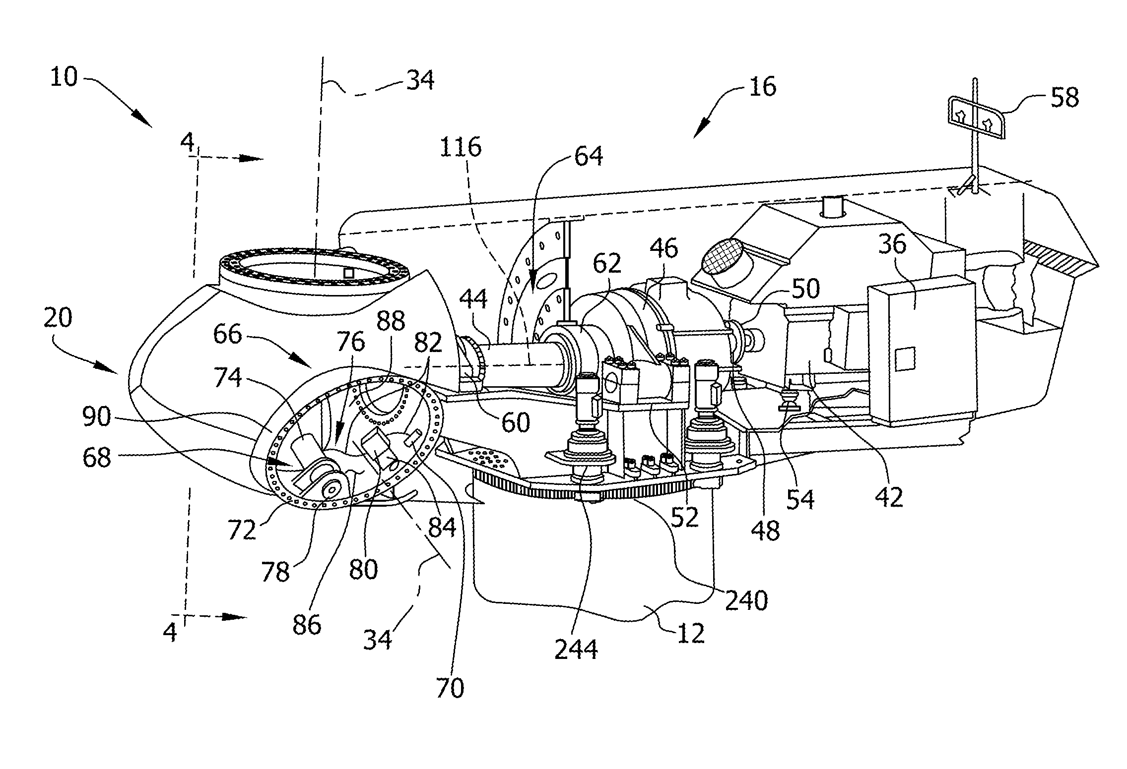
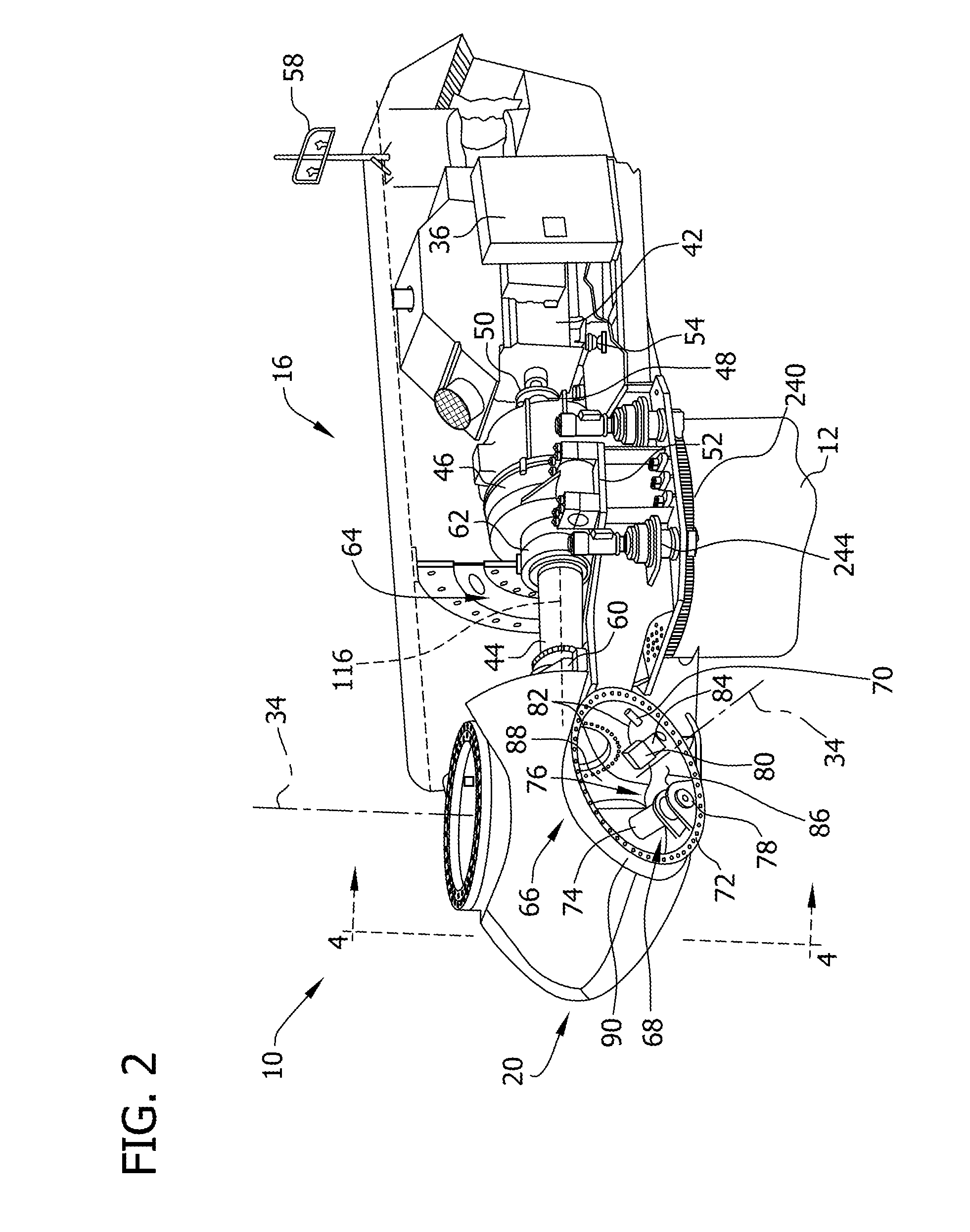
[0019]The embodiments described herein include a wind turbine system that has a hydraulic yaw drive system with improved characteristics when subjected to high wind forces. More specifically, the yaw drive system is designed such that a valve in the hydraulic system may open during high loads caused by gusts, such that the nacelle may move, in response, or, as a result of the wind force, against the torque exerted by the yaw motor, or, in other words, the nacelle may “slip” due to the high load and thus passively react to the wi...


PUM


Abstract

A yaw drive system for a wind energy system includes a hydraulic yaw motor for adjusting the yaw angle of a nacelle of a wind energy system, at least one hydraulic pump adapted for providing a pressurized hydraulic fluid, a hydraulic line system, including at least one line connecting the at least one hydraulic pump and the at least one hydraulic yaw motor, and at least one overpressure valve. The at least one overpressure valve is connected to at least one flow path of the hydraulic fluid between the at least one hydraulic pump and the at least one hydraulic motor. Further, a method for changing a yaw angle of a wind turbine nacelle is provided.

Description

BACKGROUND OF THE INVENTION[0001]The subject matter described herein relates generally to methods and systems for the yaw adjustment of wind turbines, and more particularly, to methods and systems for the hydraulic yaw adjustment of wind turbines.[0002]At least some known wind turbines include a tower and a nacelle mounted on the tower. A rotor is rotatably mounted to the nacelle and is coupled to a generator by a shaft. A plurality of blades extend from the rotor. The blades are oriented such that wind passing over the blades turns the rotor and rotates the shaft, thereby driving the generator to generate electricity.[0003]If the plane defined by the rotor blades of the wind turbine is not perpendicular to the wind, the turbine may still be operable, but the rotor blades and the nacelle, to which they are coupled via the rotor blade hub and the rotor axis, experience shear forces that lead to a large load on these parts, to wear, and, hence, to an increased need for maintenance. Ty...

Claims


Application Information

Patent Timeline
Patent Type & Authority Applications(United States)
IPC IPC(8): B64C11/06F04B49/00
CPCF03D7/0204Y02E10/723F05B2260/406Y02E10/72
Inventor EDENFELD, THOMASSIEBERS, THOMAS
Owner GENERAL ELECTRIC CO
Why Eureka
Try Eureka