Control apparatus and control method for robot arm, robot, control program for robot arm, and robot arm control-purpose integrated electronic circuit

a technology of electronic circuit and control apparatus, which is applied in the direction of electric programme control, program control, instruments, etc., can solve the problems of robot stopping or erroneously performing the task, affecting the work efficiency of the robot, and affecting the efficiency of the robo

Active Publication Date: 2011-08-25
PANASONIC CORP
View PDF7 Cites 88 Cited by
  • Summary
  • Abstract
  • Description
  • Claims
  • Application Information

AI Technical Summary

Benefits of technology

[0058]As has been described in the foregoing, according to the present invention, when the ambient environment changes, the person corrects a motion by manipulating the robot arm, whereby, when the same environment is varied nex

Problems solved by technology

However, in Patent Document 1, because the teaching person must teach all the teaching points, the teaching takes time and is very laborious .
Thus, it is inefficient.
Further, such parallel use with programming, involving the use of a remote apparatus such as a teaching pendant, in

Method used


Image

  • Control apparatus and control method for robot arm, robot, control program for robot arm, and robot arm control-purpose integrated electronic circuit
  • Control apparatus and control method for robot arm, robot, control program for robot arm, and robot arm control-purpose integrated electronic circuit
  • Control apparatus and control method for robot arm, robot, control program for robot arm, and robot arm control-purpose integrated electronic circuit

Examples


first embodiment

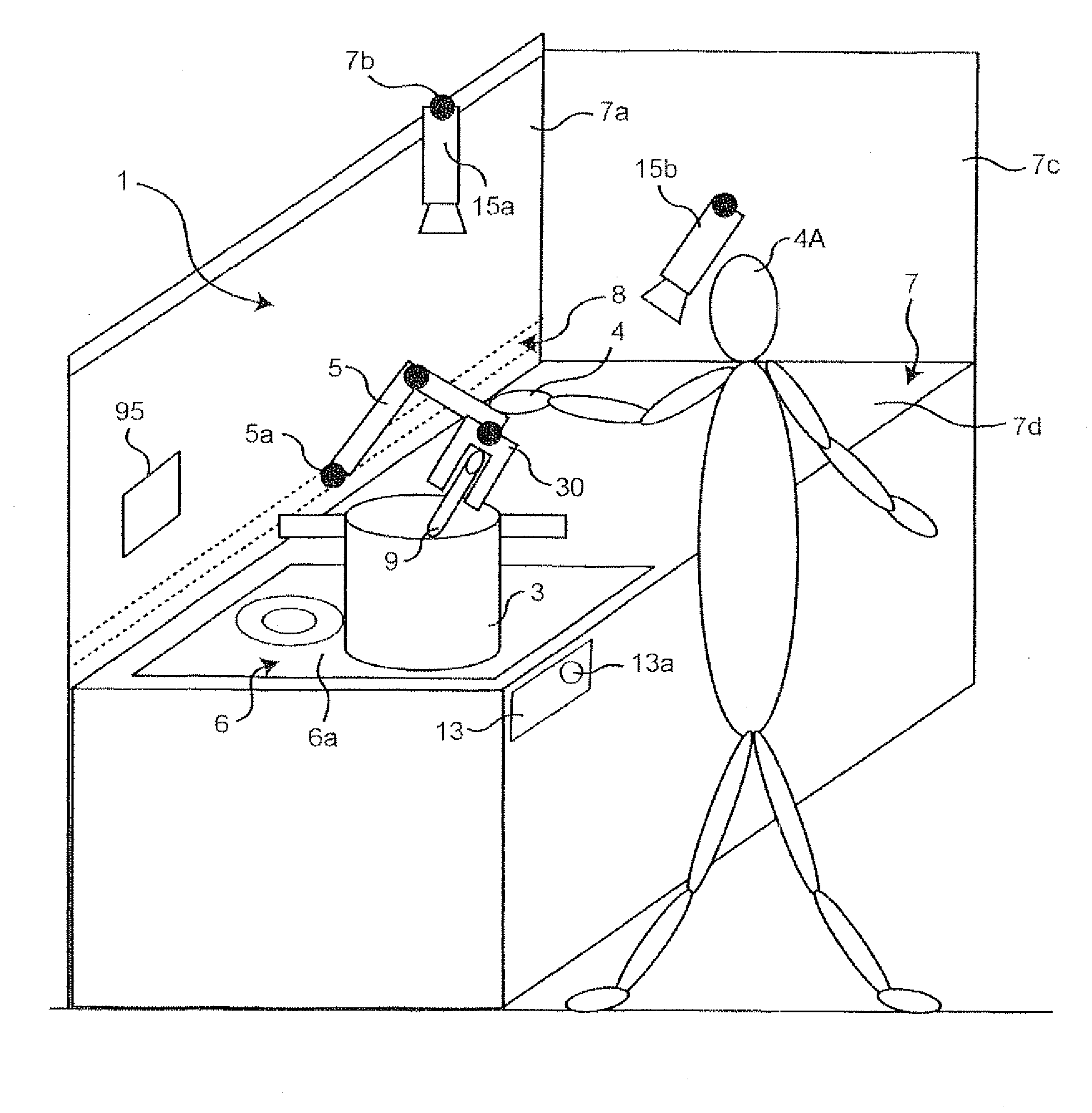
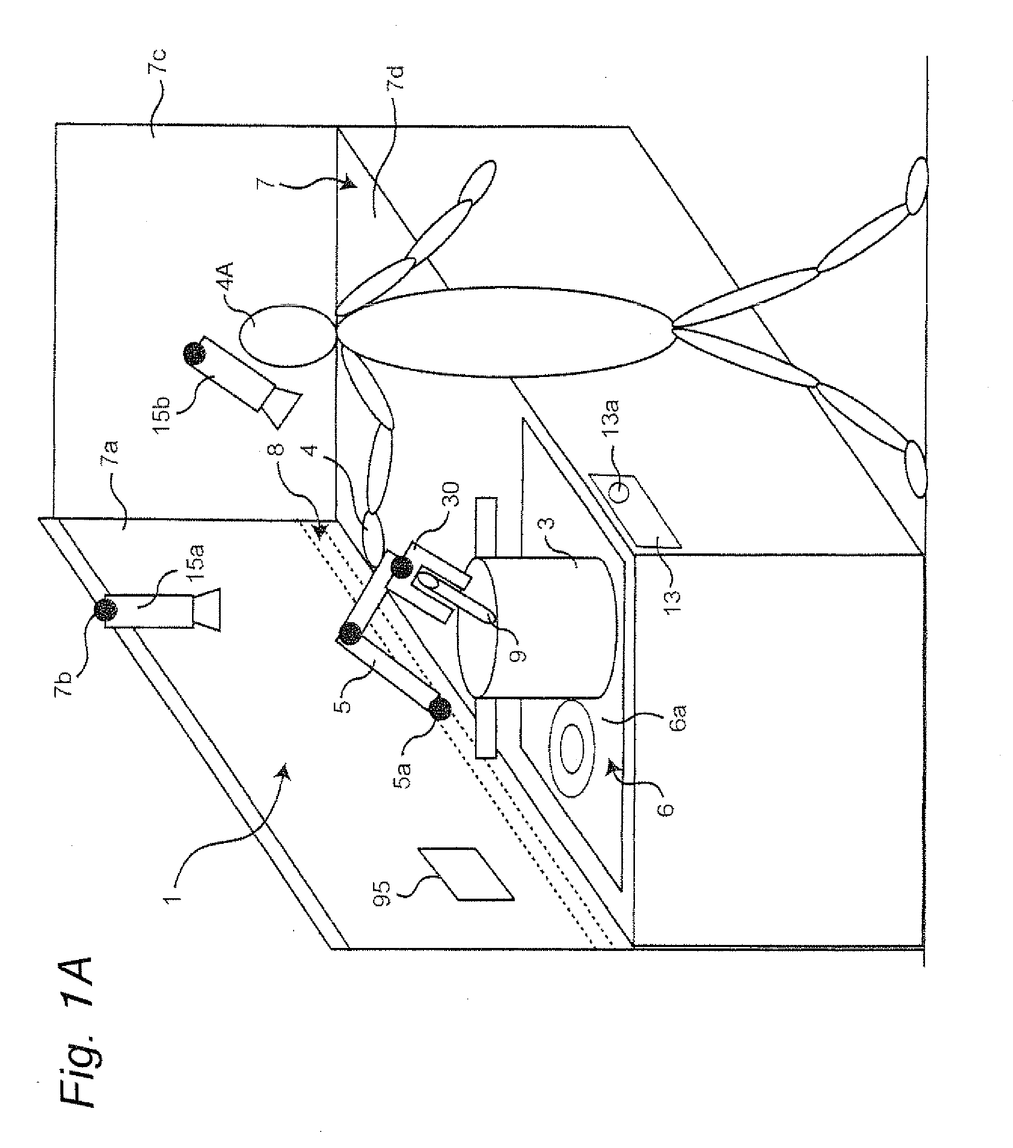
[0212]A description will be given of the structure of a robot 1 including a robot arm and a control apparatus therefor according to a first embodiment of the present invention.

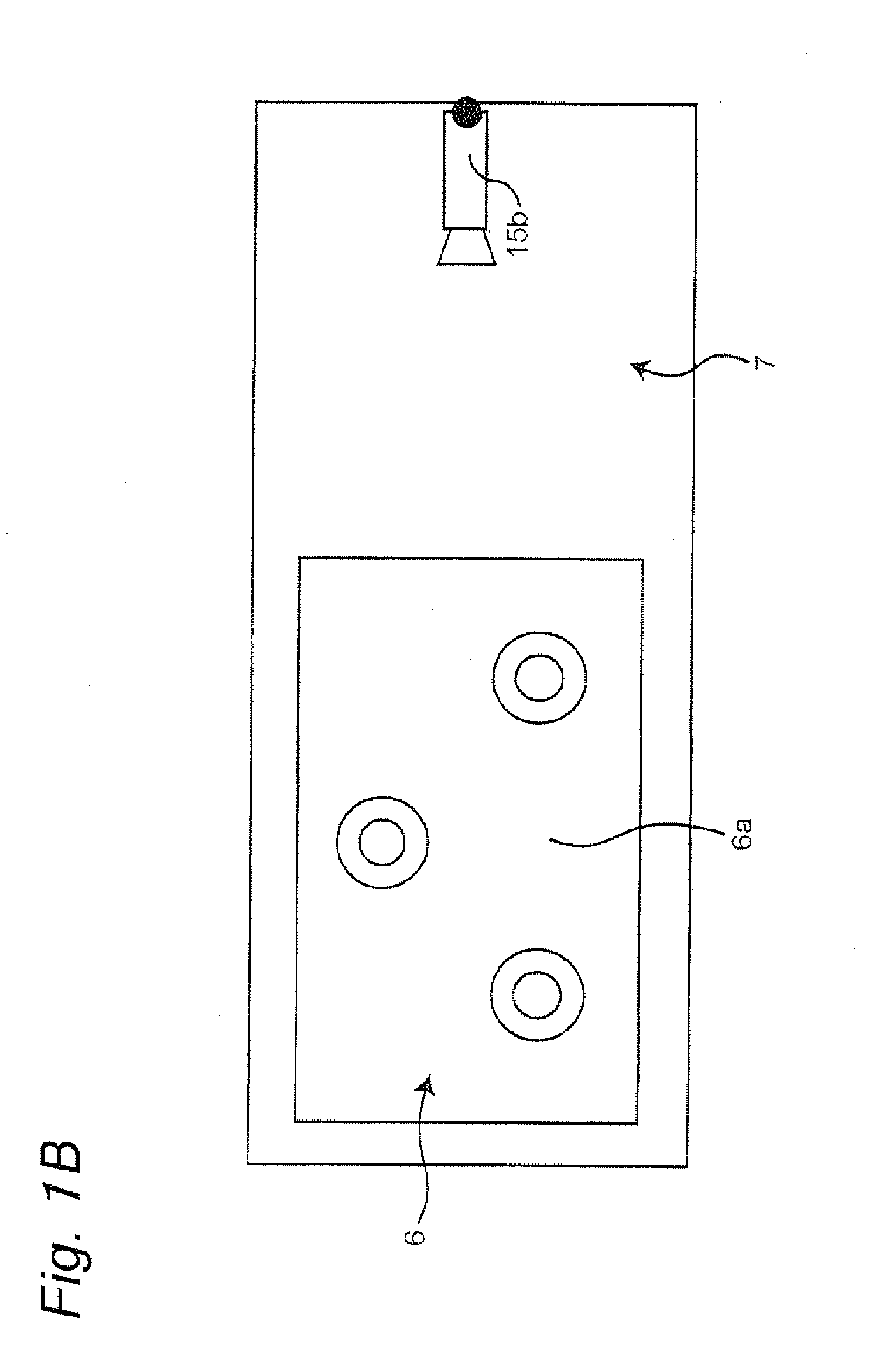
[0213]FIG. 1A shows an overview of the robot 1 including a robot arm 5 and a control apparatus 70 that controls the drive motion of the robot arm 5, according to the first embodiment of the present invention. FIG. 13 is a top view of a workbench 7 shown in FIG. 1A at which the robot arm 5 performs a task, and FIG. 10 is a front view of the workbench 7 and a pot 3 shown in FIG. 1A.

(Apparatus Structure)

[0214]As shown in FIG. 1A, the robot arm 5 of the robot 1 is installed on a wall surface 7a of the workbench 7 such as a household kitchen or a table, for example. Abase end 5a of the robot arm 5 is shiftably supported by a rail 8 fixed to the wall surface 7a, such that the robot arm 5 can shift on the rail 8 along therewith in a lateral direction (e.g., in the horizontal direction) by a force of a hand 4 of a per...

second embodiment

[0490]The basic structure of a robot arm 5 and a control apparatus therefor according to a second embodiment of the present invention is similar to that in the first embodiment. Therefore, the description as to the common constituents is not repeated herein, and the difference from the first embodiment solely will be detailed in the following.

[0491]As shown in FIG. 19A, a description will be given of an exemplary case where a wipe-cleaning task is performed for a top board 6a of an IH cooking heater 6 through the use of a robot 1 including the robot arm 5 and the robot arm 5 control apparatus. To a hand 30 of the robot arm 5, a sponge 46 as one example of a wipe-cleaning task-use jig being one example of the task-target object is attached.

[0492]First, as a comparative example, a description will be given of a case where, being different from the present invention, every time a contamination occurs (when a contaminated portion is found), the person 4A must perform a correction manipu...

third embodiment

[0539]The basic structure of a robot arm 5 and a control apparatus therefor according to a third embodiment of the present invention is similar to that in the first embodiment. Therefore, the description as to the common constituents is not repeated herein, and the difference from the first embodiment solely will be detailed in the following.

[0540]In the third embodiment, a description will be given of an exemplary case where, as shown in FIG. 21, a screw 73 is attached to a device 71 such as a television set, a DVD recorder or the like in a factory employing cell manufacturing, through the use of a robot 1 including the robot arm 5 and the control apparatus for the robot arm 5. A tool for attaching the screw 73 as one example of the task-use jig can be attached to the hand 30 of the robot arm 5.

[0541]As shown in FIG. 21, the robot arm 5 of the robot 1 is installed on a wall surface 7a of a workbench 7 such as a workbench table in a factory, for example. The base end of the robot ar...


PUM


Abstract

Motion information of a robot arm stored in a motion information database is acquired. A person manipulates the robot arm, and correction motion information at the time of the motion correction is acquired. An acquiring unit acquires environment information. A motion correction unit corrects the motion information while the robot arm is in motion. A control rule generating unit generates a control rule for allowing the robot arm to automatically operate based on the corrected motion information and the acquired environment information. The motion of the robot arm is controlled based on the generated control rule.

Description

[0001]This is a continuation application of International Application No. PCT / JP2010 / 005705, filed Sep. 21, 2010.BACKGROUND OF THE INVENTION[0002]The present invention relates to a control apparatus and a control method for a robot arm for generating and teaching a motion of a robot arm, a robot including a control apparatus for a robot arm, a control program for a robot arm, and a robot arm control-purpose integrated electronic circuit.[0003]In recent years, household robots such as nursing-care robots, housework assistant robots, or the like have actively been developed. Being different from industrial robots, such household robots are manipulated by laymen at home and, therefore, the motion thereof must simply be taught. Further, because the motion environment in which the robots perform tasks varies depending on each home, such robots must flexibly address a great variety of household environments.[0004]An exemplary teaching method for a robot apparatus is performed as follows ....

Claims


Application Information

Patent Timeline
IPC IPC(8): B25J9/22B25J13/02B25J19/04
CPCB25J9/1664G05B2219/40424B25J13/08
Inventor TSUSAKA, YUKO
Owner PANASONIC CORP
Why Eureka
Try Eureka