Heat pump defrost control

a heat pump and control technology, applied in the field of heat pumps, can solve the problems of reducing the efficiency of a heat pump and one of the more expensive repairs of the reverse valve, and achieve the effect of reducing the shock of the system

Inactive Publication Date: 2011-09-01
LAWSON SR REYNOLD KENNETH
View PDF5 Cites 5 Cited by
  • Summary
  • Abstract
  • Description
  • Claims
  • Application Information

AI Technical Summary

Benefits of technology

[0055]The present invention has timers incorporated so as to alleviate system shock by idling heat pump for a period of time and then i

Problems solved by technology

Even a small blow-by leak can reduce the efficiency of a heat pump considerably.

Method used


Image

  • Heat pump defrost control
  • Heat pump defrost control
  • Heat pump defrost control

Examples


Embodiment Construction

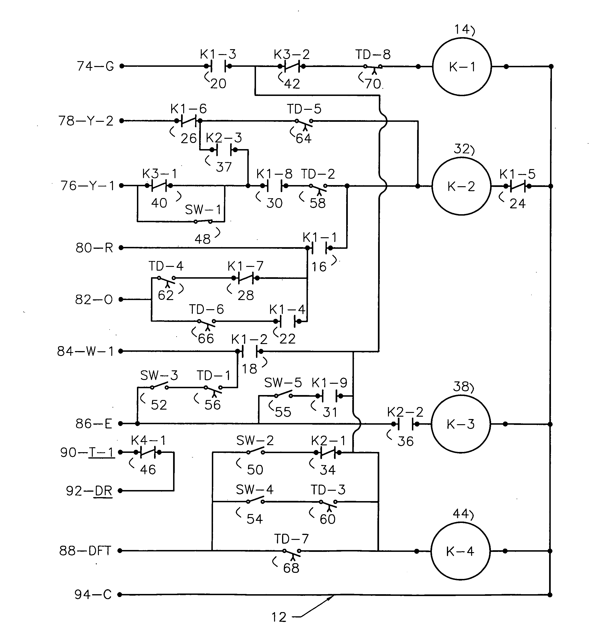
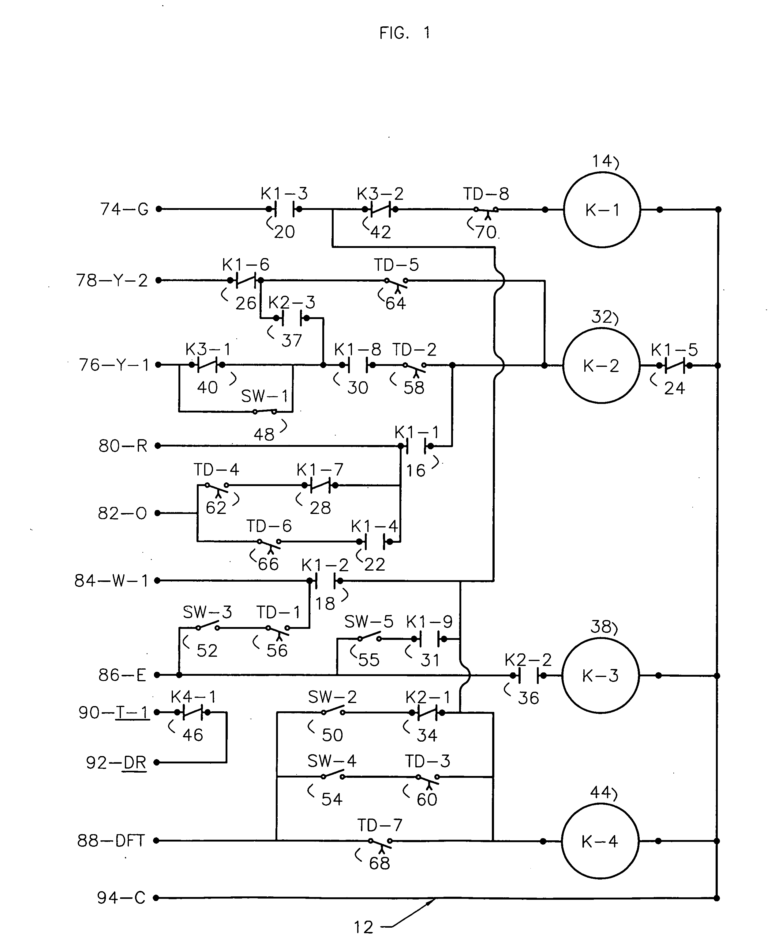
[0087]Referring to the drawing FIG. 1, a schematic diagram is shown front view of an off-cycle heat pump defrost control 12 embodying the present invention with circuits to be etched and parts mounted on a PCB to be installed in the junction box of a package or split unit (outdoor condenser) with connections 74 through 94 made

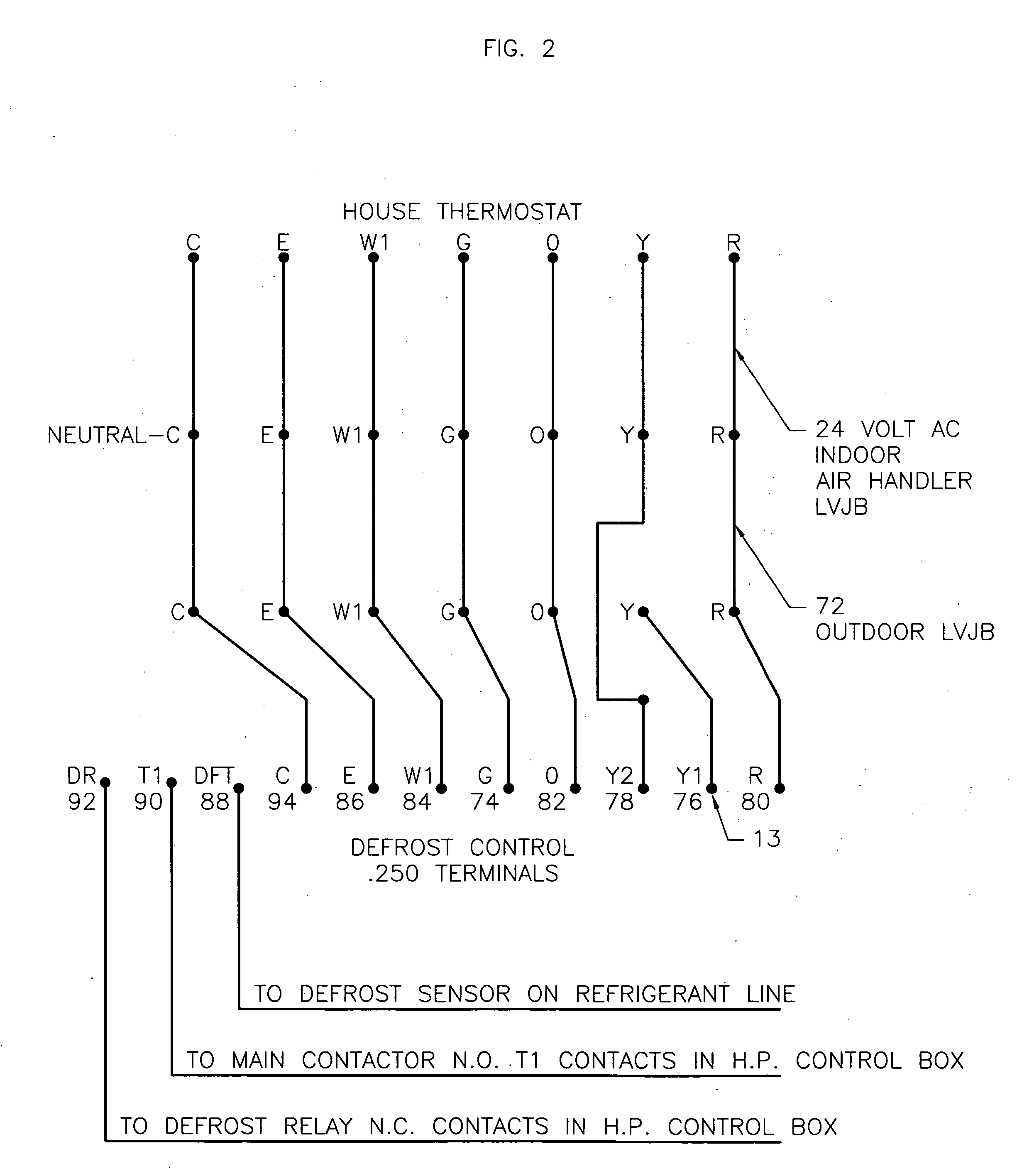
[0088]In reference to connection diagram 13FIG. 2 for split heat pump units, the defrost control board connections 13 are the same as the package units 12. The defrost board section 13 is the only relevant part to the present invention. 13 has the the same reference numbers as 12. The remainder of drawing 13 which includes the thermostat, air handler, and the outdoor low voltage junction box, is shown for Illustration purposes.

[0089]To further clarify the connections and the purpose of the circuits in FIGS. 1 and 2 referenced by identification numbers as follow:[0090]G-74—Controls blower motor paralleled with existing green conductor in LVJB 72.[0091]Y1-76—Conn...


PUM


Abstract

An electronic defrost system consisting of a circuit board designed to implement defrost cycle of an air source heat pump outdoor coil during the off-cycle period. off-cycle is when the house thermostat is satisfied, heat pump is timed off for two minutes and then reactivated in regular defrost cycle if defrost sensor is calling for defrost. (Temp/off cycle). When sensor opens, heat pump will shut off for two minutes to allow pressure equalization.
The automatic emergency heat is an option that can be selected. The automatic setting will activate the same circuit as the manual switch at the indoor house thermostat.
Defrost control board designed to activate all heat strips during defrost cycle if desired.

Description

INCORPORATION BY REFERENCE[0001]Title: Defrost system and method for heat pumps[0002]Inventor: Shaw, David N.[0003]Date: Mar. 10, 2009[0004]Application Ser. No. 12 / 401,136[0005]Specific reference: Paragraph [0002]-[0005][0006]The description goes into great detail how a heat pump defrost system operates.SCHEMATIC AND CONNECTION LEGEND[0007]12—Heat pump defrost control circuit board drawing[0008]13—Split unit connection drawing[0009]14—K-1 Defrost relay coil—24 volts[0010]16—K1-1 Energizes main contactor on heat pump[0011]18—K1-2 Energizes auxiliary heat during defrost cycle[0012]20—K1-3 Activates blower motor relay[0013]22—k1-4 Shifts reversing valve to cool mode for defrosting outdoor coil[0014]24—K1-5 Interlocks K-2 during defrost cycle[0015]26—K1-6 Interlocks Y-2[0016]28—K1-7 Energizes TD-4[0017]30—K1-8 Prevents voltage feedback in running mode[0018]31—K1-9 Activates all heat strips[0019]32—K-2 Normal running mode coil—24 volts[0020]34—K2-1 Interlocks defrost coil K-1[0021]36—K2-...

Claims


Application Information

Patent Timeline
IPC IPC(8): F25D21/06
CPCF24F2011/0089F25D21/006F25B30/02F24F11/42
Inventor LAWSON, SR., REYNOLD KENNETH
Owner LAWSON SR REYNOLD KENNETH
Why Eureka
Try Eureka