Sensor-equipped bearing for wheel

a technology for bearings and wheels, applied in the direction of instruments, force/torque/work measurement apparatus, transportation and packaging, etc., can solve the problems of increasing the cost, difficult to achieve the procedure of drawing a signal cable from the inside of the bearing assembly to the outside of the bearing assembly and the assemblage of the sensor unit, and the sensor is apt to be damaged. , to achieve the effect of accurate detection and convenient press fitting

Active Publication Date: 2011-09-01
NTN CORP
View PDF15 Cites 12 Cited by
  • Summary
  • Abstract
  • Description
  • Claims
  • Application Information

AI Technical Summary

Benefits of technology

[0045]According to the construction described above, the electronic components including the plurality of the sensor units for detecting the load, the signal processing IC for processing the respective output signals of the sensors and the signal cable for transmitting the processed output signal to the outside of the bearing assembly are fitted to the outer peripheral surface of the stationary member in a fashion coaxial with the stationary member and, at the same time, the sensor assembly is covered with the protective covering of a type having the inner diameter increasing towards the inboard side. Since the inboard end of this protective covering is mounted on the outer peripheral surface of the stationary member and the outboard end of the protective covering is fitted to the outer peripheral surface of the stationary member through the sealing ring made of the elastic element, the sensor assembly can be covered with the protective covering and damages to the sensors under the influence of the ambient environment are prevented so as to enable the load acting on the wheel support bearing assembly or the tire tread surface to be accurately detected for an extended period of time.
[0046]In the present invention, the protective covering may be of a stepped cylindrical configuration with its inboard end having a large diameter. The use of the protective covering of the stepped cylindrical configuration with its inboard end having a large diameter advantageously facilitates press fitting of the protective covering onto the outer peripheral surface of the stationary member from the outboard side of the stationary member.

Problems solved by technology

For this reason, the sensor is apt to be damaged once small stones on the road, when bounced during the travel of the automotive vehicle, strike against the sensor or once a muddy water is splattered on the sensor during the travel of the automotive vehicle.
On the other hand, according to the structure disclosed in the Patent Document 3 listed above, the sensor unit is fitted to the inner diametric surface of the outer ring of the wheel support bearing assembly and, therefore, the sensor can be protected from the ambient environment, but a procedure to draw a signal cable from inside of the bearing assembly to the outside of the bearing assembly and assemblage of the sensor unit are difficult to achieve.
(1) The number of component parts used increases, accompanied by an increase of the cost and, therefore, reduction in weight is unable to be accomplished.

Method used


Image

  • Sensor-equipped bearing for wheel
  • Sensor-equipped bearing for wheel
  • Sensor-equipped bearing for wheel

Examples


first embodiment

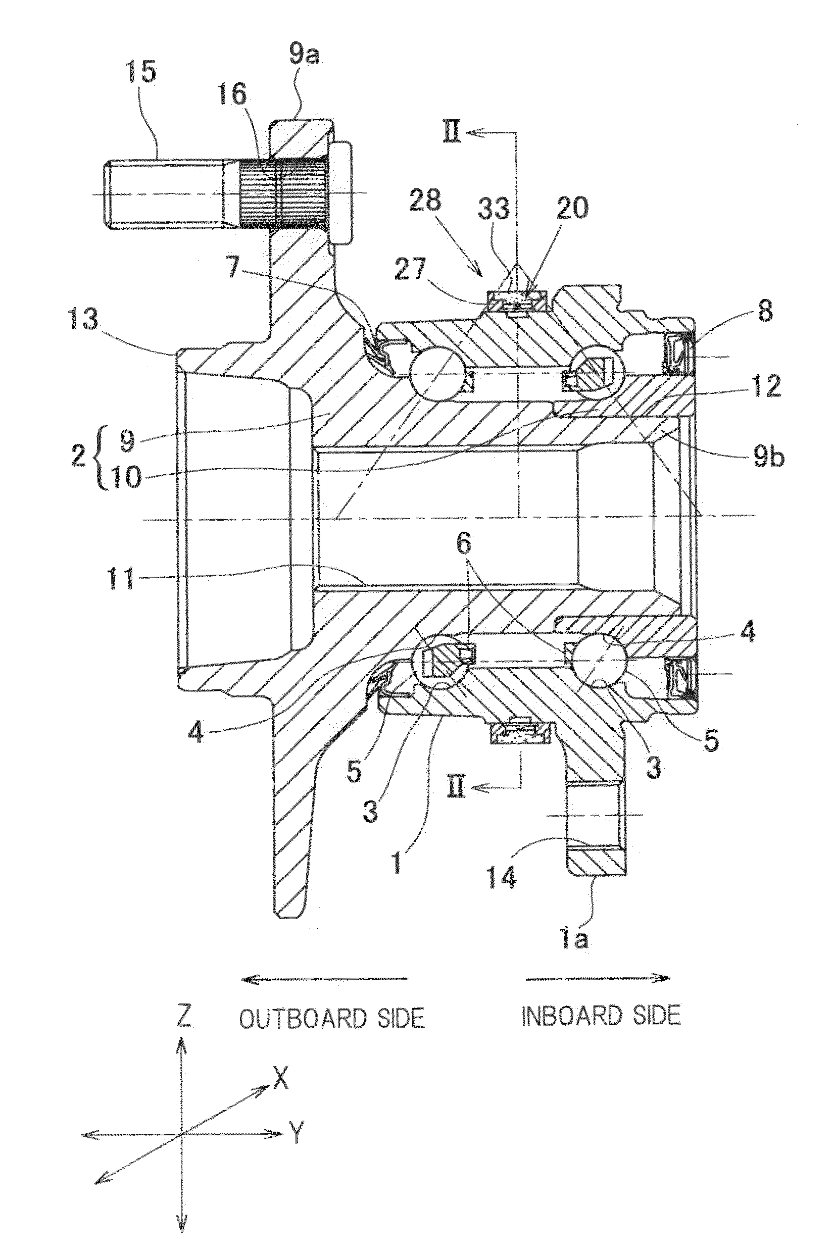
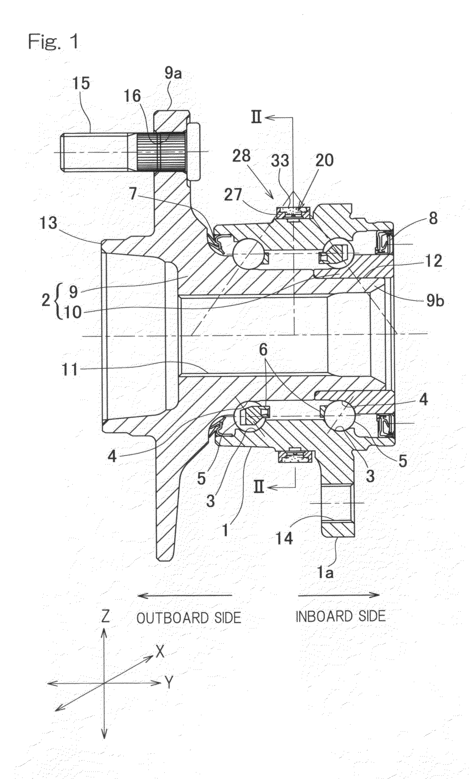
[0144]The sensor equipped wheel support bearing assembly according to the present invention includes, as best shown in FIG. 1 in a sectional representation, an outer member 1 having an inner periphery formed with double row rolling surfaces 3, an inner member having an outer periphery formed with rolling surfaces 4 held in face-to-face relation with the respective rolling surfaces 3, and double row rolling elements 5 interposed between the respective rolling surfaces 3 and 4 in the outer and inner members 1 and 2. This wheel support bearing assembly is rendered to be a double row angular contact ball bearing type, in which the rolling elements 5 are in the form of balls and each row of the rolling elements 5 are retained by a retainer 6. The rolling surfaces 3 and 4 represent an arcuate sectional shape and are so formed as to have respective ball contact angles held in back-to-back relation to each other. Opposite annular ends of a bearing space delimited between the outer member 1 ...

second embodiment

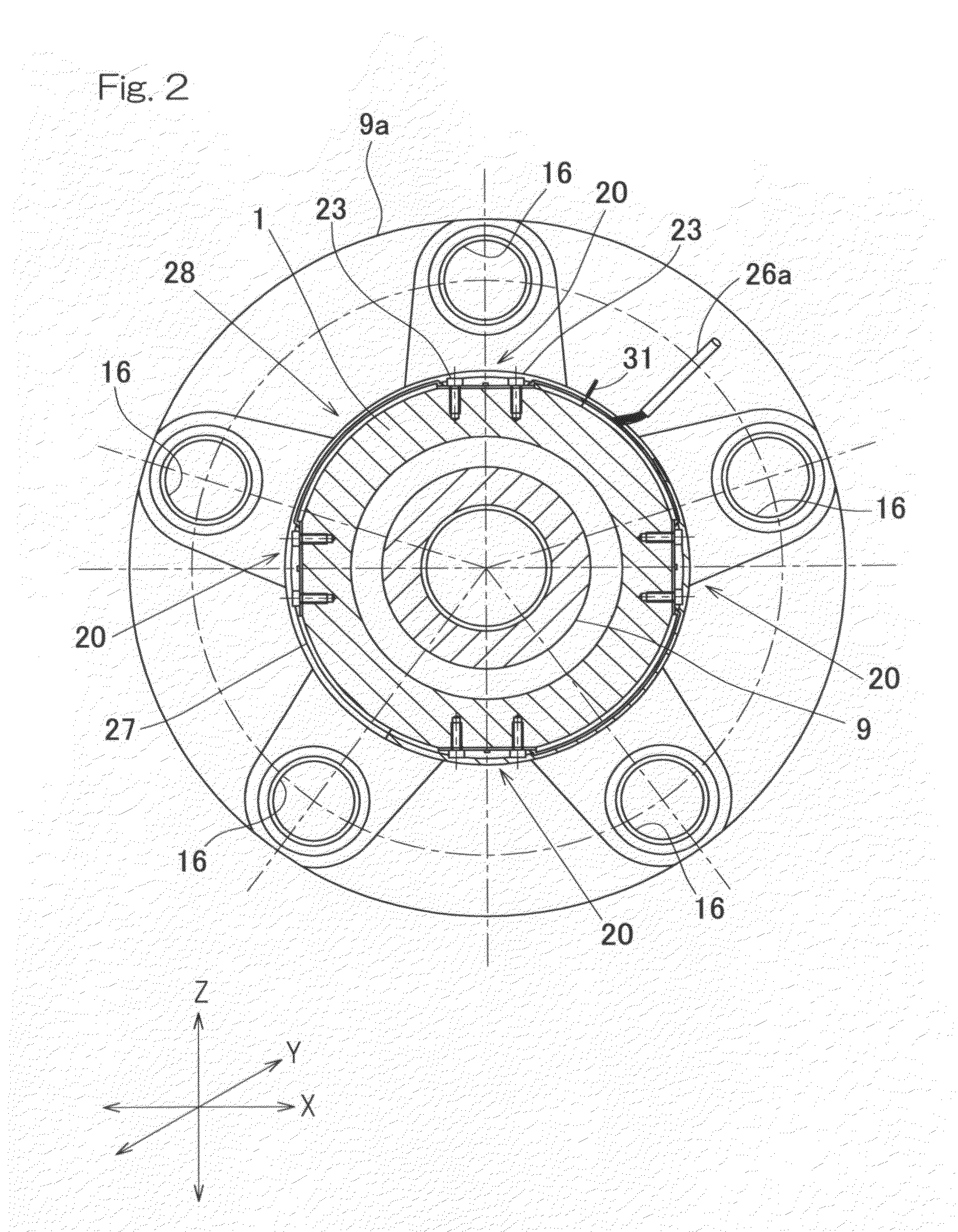
[0172]In the practice of this second embodiment, each of the sensor units 20 provided on the outer diametric surface of the outer member 1 serving as the stationary member, is arranged inwardly of the annular protective covering 27, best shown in FIGS. 21A and 21B respectively in front elevational and side views, together with an electronic component including a signal processing IC 25 which is an integrated circuit chip for processing an output signal of the strain sensor 22, a wiring portion 26b (FIGS. 23A and 23B) of the signal cable 26 for transmitting the processed output signal to the outside of the bearing assembly and a flexible substrate 35 having a wiring circuit 36 for wiring among the sensor unit 20, the signal processing IC 25 and the signal cable wiring portion 26b, to thereby provide an annular sensor assembly 28 best shown in FIGS. 27A and 27B in front elevational and side views.

[0173]FIGS. 23A and 23B illustrate the electronic components that are arranged inside the...

third embodiment

[0213]In this third embodiment described above, the sealing member 40 is made up of the ring shaped core metal 41 following the inner diametric surface of the protective covering 27 and the pair of the ring shaped elastic segments 42 jointed to the entire circumferences of opposite side edges of the core metal 41 so as to range from an inner diametric surface thereof to the outer diametric surface thereof. Accordingly, the elastic segments 42 on the opposite side edges of the sealing member 40 are sandwiched between the outer diametric surface of the outer member 1 and the inner diametric surface of the protective covering 27 to thereby completely shield the interior of the protective covering 27 from the outside, and therefore, the sealing effect brought about by the sealing member 40 can be increased.

[0214]Also, since in this third embodiment described above, the core metal 41 of the sealing member 40 is in the form of a product prepared by means of any known press work with the u...


PUM

PropertyMeasurementUnit
thicknessaaaaaaaaaa
widthaaaaaaaaaa
areaaaaaaaaaaa

Abstract

A wheel support bearing assembly includes rolling elements (5) interposed between double row rolling surfaces (3, 4) of outer and inner members (1, 2), which are opposed to each other. Electronic components including a plurality of the sensor units (20), a signal processing IC (25) for processing respective sensor output signals thereof and a signal cable (26) for transmitting the processed output signal to the outside of the bearing assembly are arranged inwardly of an annular protective covering (27) to provide an annular sensor assembly (28). The sensor assembly (28) is fitted to a peripheral surface of a stationary member in a fashion coaxial with the stationary member.

Description

CROSS REFERENCE TO THE RELATED APPLICATION[0001]This application is a continuation application, under 35 U.S.C §111(a) of international application No. PCT / JP2009 / 005735, filed Oct. 29, 2009, which claims priority to Japanese patent applications No. 2008-284079, filed Nov. 5, 2008, No. 2008-302296, filed Nov. 27, 2008, No. 2008-314164, filed Dec. 10, 2008, No. 2008-324965, filed Dec. 22, 2008, and No. 2009-022215, filed Feb. 3, 2009, the entire disclosure of all of which is herein incorporated by reference as a part of this application.BACKGROUND OF THE INVENTION[0002]1. Field of the Invention[0003]The present invention relates to a sensor equipped wheel support bearing assembly having a load sensor built therein for detecting a load imposed on a bearing unit for a vehicle wheel.[0004]2. Description of Related Art[0005]As a technique for detecting a load acting on each of vehicle wheels, a sensor equipped wheel support bearing assembly has been suggested (in for example, the Patent ...

Claims


Application Information

Patent Timeline
Patent Type & Authority Applications(United States)
IPC IPC(8): G01L1/22
CPCB60B27/0005B60B27/0068B60B27/0094G01L5/0019F16C19/522F16C2326/02G01L1/2231F16C19/186F16C2233/00F16C41/00B60B35/18G01L5/00
Inventor ONO, YUJIRONISHIKAWA, KENTAROUKAMETAKA, KOJINORIMATSU, TAKAYUKIIKKI, KENTAROTAKAHASHI, TORU
Owner NTN CORP
Why Eureka
Try Eureka