This helps you quickly interpret patents by identifying the three key elements:
Problems solved by technology
Method used
Benefits of technology
Benefits of technology
[0010]The object of the present invention is to at least partially obviate the above drawbacks, by providing a hose with a double textile knitted layer that can be manufactured in a much simpler and quicker manner than homologous prior art hoses, while maintaining optimal anti-kink and burst pressure performances.
[0012]With this configuration, the hose can be manufactured in a highly simple, inexpensive and quick manner, while maintaining good anti-kink and burst pressure properties.
[0020]The wales of stitches of both textile knitted layers may be substantially parallel to the axis, to optimize simplicity, throughput and cost effectiveness of hose fabrication.
[0028]Advantageously, the needles of both series of needles may face towards each other to optimize simplicity, throughput and cost effectiveness of hose fabrication.
Problems solved by technology
While this prior art hose has good anti-kink properties and a higher burst pressure than the hose with a single textile layer, it still has the drawbacks of difficult manufacture and relatively poor throughput.
Method used
Image
Click on the blue label to locate the original text in one second.
Reading with bidirectional positioning of images and text.
Examples
first embodiment
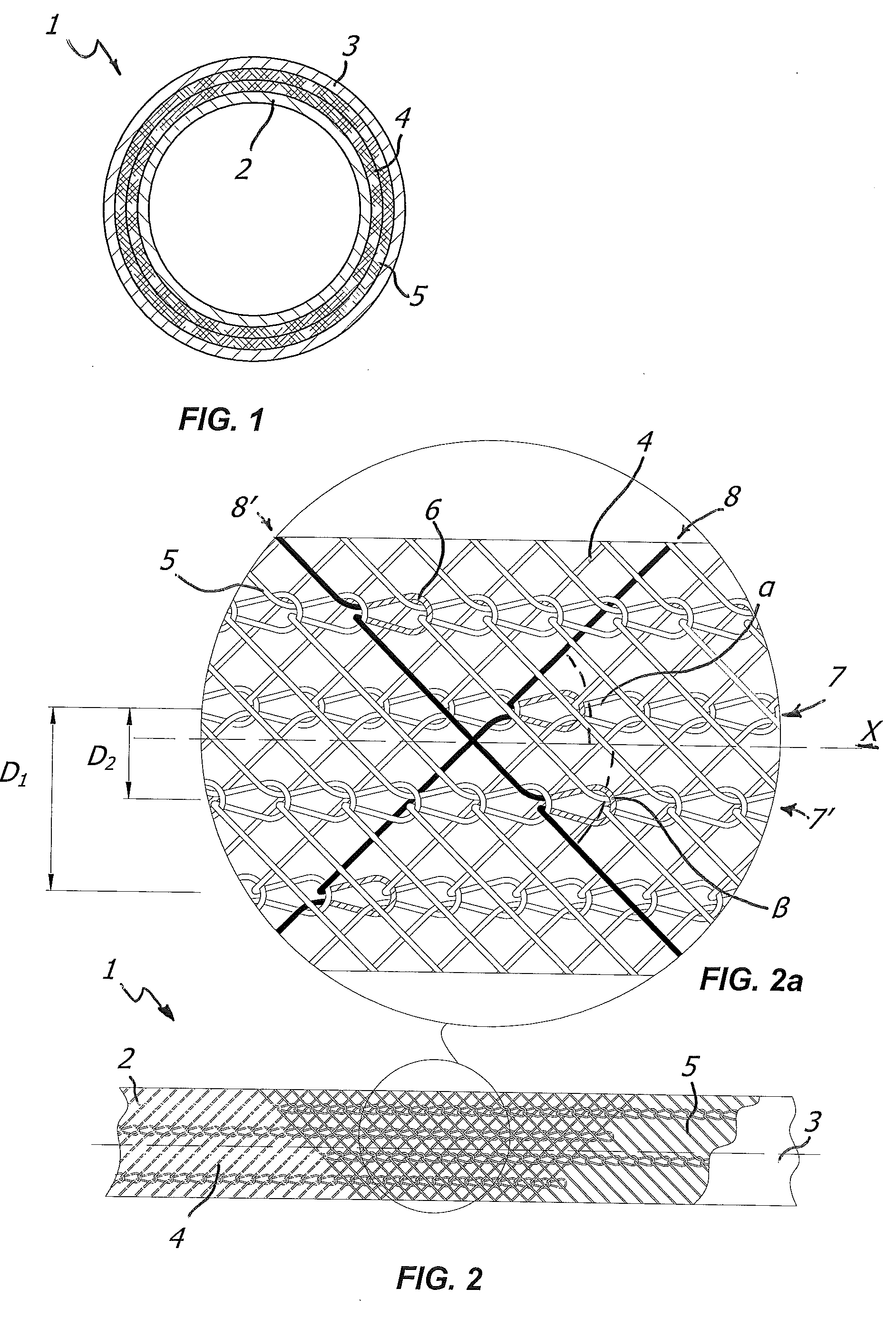
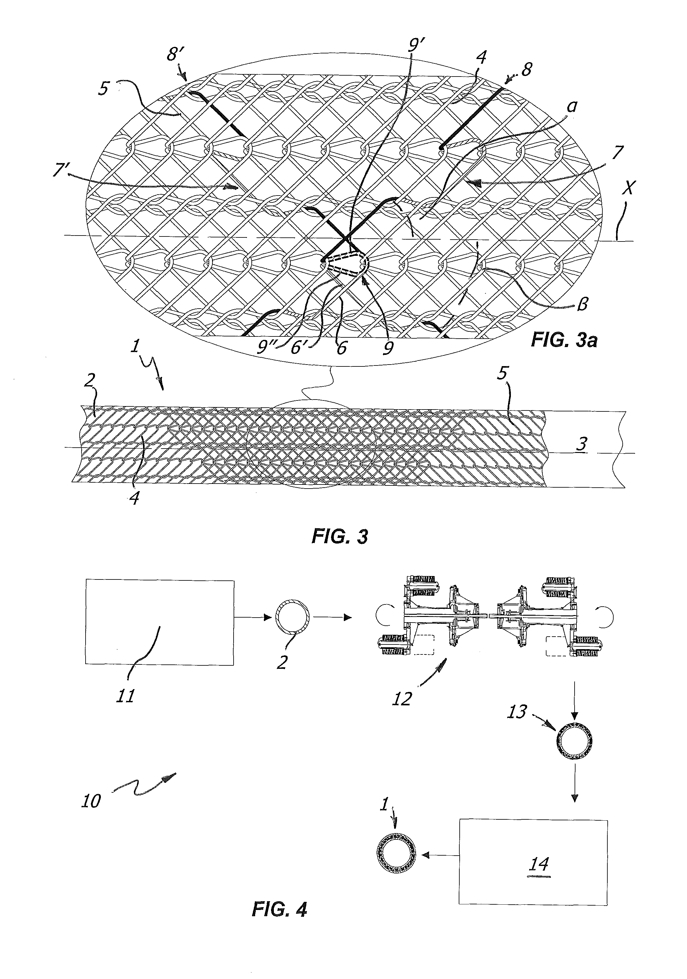
[0046]As particularly shown in FIG. 2, which represents a hose according to the invention, the lines of stitches 7 of the first textile layer 4 have a circumferential pitch or predetermined distance D1, whereas the wales of stitches 7′ of the second textile layer 5 have a distance D2 from the wales of stitches 7 of the first layer 4 that is substantially half the distance D1. This feature allows the wales of stitches 7, 7′ to be evenly spaced along the periphery of the substrate 2, thereby considerably increasing the burst pressure of the hose 1.
[0047]In an alternative embodiment, the wales of stitches 7, 7′ may also be in side-by-side relation.
[0048]The hose 1 may be fabricated by the manufacturing line as shown in FIG. 4.
[0049]At first, the substrate 2 designed to act as a supporting layer is extruded in a manner known per se, by introducing plasticized PVC into a first extruder 11.
[0050]Then, the supporting layer will be introduced into a knitting station 12, adapted to form the ...
second embodiment
[0061]Conversely, in the apparatus according to FIG. 6, such movements have the same directions, so that the forward motion of a needle of the first series 26 towards a central reference plane causes the needle aligned therewith in the second series 27 to move away from the same central reference plane.
[0062]In both embodiments, the cam means will be appropriately sized and / or configured to obtain the above described effect.
[0063]As a result, with the apparatus of the first embodiment, the stitches of both textile layers will be knit stitches, whereas in the second embodiment, the stitches of the underlying layer will be knit stitches, as shown in FIG. 2, whereas the second stitches will be purl stitches, as shown in FIG. 8.
[0064]The apparatus 20 includes motor means, not shown and known per se, which are adapted to rotate the reel-supporting plates 36, 37 in opposite directions, e.g. one clockwise V1 and the other counterclockwise V2.
[0065]Thus, the first knitting section 22 will f...
PUM
Property
Measurement
Unit
Time
aaaaa
aaaaa
Time
aaaaa
aaaaa
Angle
aaaaa
aaaaa
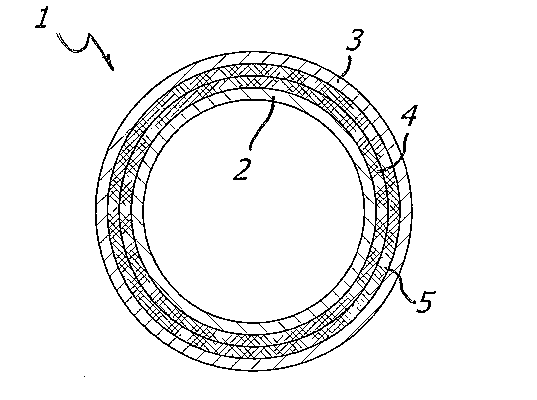
Abstract
A multilayer flexible irrigation hose includes an inner layer made of a first thermoplasticpolymer material, an outer layer made of a second thermoplasticpolymer material, and a first textile reinforcement layer and a second textile reinforcement layer in mutually overlapping relation. The first and second textile reinforcement layers are knitted with stitches of the tricot type, having wales of stitches and lines of stitches. The lines of stitches of said first and second textile layers have opposite inclinations to the longitudinal axis of the hose, and the wales of stitches of at least one of said first and second textile layers are substantially parallel to said longitudinal axis. A method of making said hose, a line for manufacturing same and a knitting apparatus for making such hose are also disclosed.
Description
FIELD OF INVENTION[0001]The present invention generally finds application in the art of flexible hoses, and particularly relates to an irrigation hose having a double knitted layer.[0002]The invention also relates to a method of making such hose, a line for manufacturing the same and a knitting apparatus for making such hose.BACKGROUND ART[0003]Flexible hoses having a single textile layer are known in the art, and comprise an inner layer susceptible of contacting the liquid to be carried, an outer layer susceptible of being held by a user, and a textile tricot layer therebetween. One example of such hose is known from European Patent EP-B1-0623776.[0004]In such prior art hose, the wales of stitches and the lines of stitches of the textile layer have opposite inclinations to the axis of the hose.[0005]Such hose has good anti-kink properties and a relatively high burst pressure. It can be also manufactured in a simple and quick manner.[0006]Flexible hoses having a double textile knitt...
Claims
Application Information
Patent Timeline
Application Date:The date an application was filed.
Publication Date:The date a patent or application was officially published.
First Publication Date:The earliest publication date of a patent with the same application number.
Issue Date:Publication date of the patent grant document.
PCT Entry Date:The Entry date of PCT National Phase.
Estimated Expiry Date:The statutory expiry date of a patent right according to the Patent Law, and it is the longest term of protection that the patent right can achieve without the termination of the patent right due to other reasons(Term extension factor has been taken into account ).
Invalid Date:Actual expiry date is based on effective date or publication date of legal transaction data of invalid patent.

