Control apparatus for electric rotating machine

a control apparatus and electric rotating machine technology, applied in the direction of dynamo-electric converter control, dynamo-electric gear control, motor/generator/converter stopper, etc., can solve the problem of unfavorable control of the motor, torque generation in the motor, and serious problems, so as to reduce the change of the current vector

Inactive Publication Date: 2011-09-01
DENSO CORP
View PDF28 Cites 24 Cited by
  • Summary
  • Abstract
  • Description
  • Claims
  • Application Information

AI Technical Summary

Benefits of technology

[0016]Specifically, the command voltage corrector serves to minimize the change in vector of the current due to a change in rotation angle of the electric rotating machine.

Problems solved by technology

If the measured value has an error, the orientation of the phase of the motor-energizing current to the d-axis based on the measured value may result in generation of torque in the motor.
Additionally, the factor that the torque does not become zero (0) is also attributed to an error in the above torque equation.
This may cause the torque to be produced undesirably even when the phase of the motor-energizing current is oriented to the d-axis in the control of energization of the motor.
Such a problem is becoming serious with an increase in use of permanent magnet motors equipped with concentrated windings in which the space harmonics will appear strongly.
When the direction of the vector of current in the fixed coordinate system is changed to fix the phase of current provided to energize the electric rotating machine, it may cause the torque continues to be produced in the electric rotating machine.

Method used


Image

  • Control apparatus for electric rotating machine
  • Control apparatus for electric rotating machine
  • Control apparatus for electric rotating machine

Examples


first embodiment

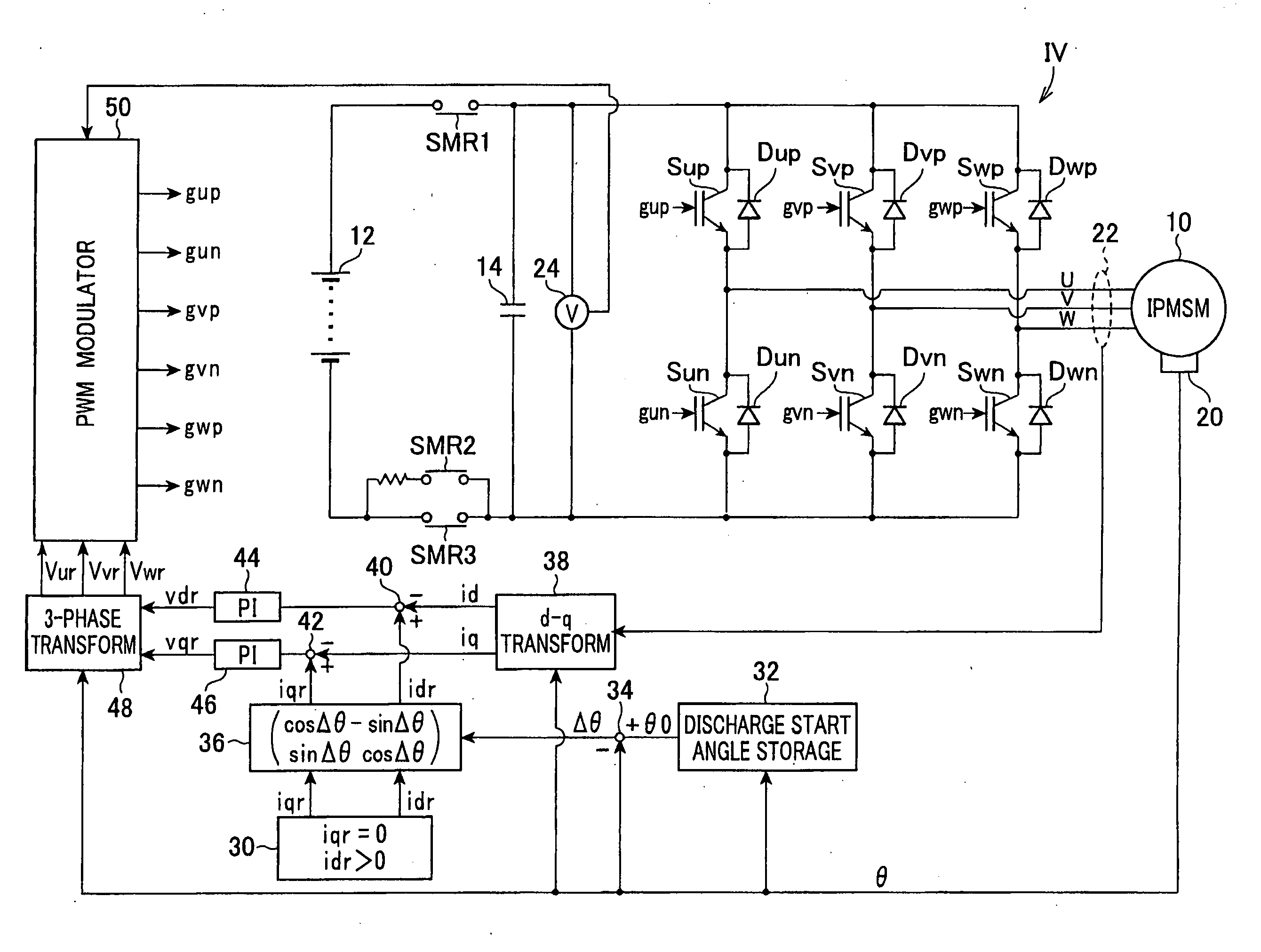
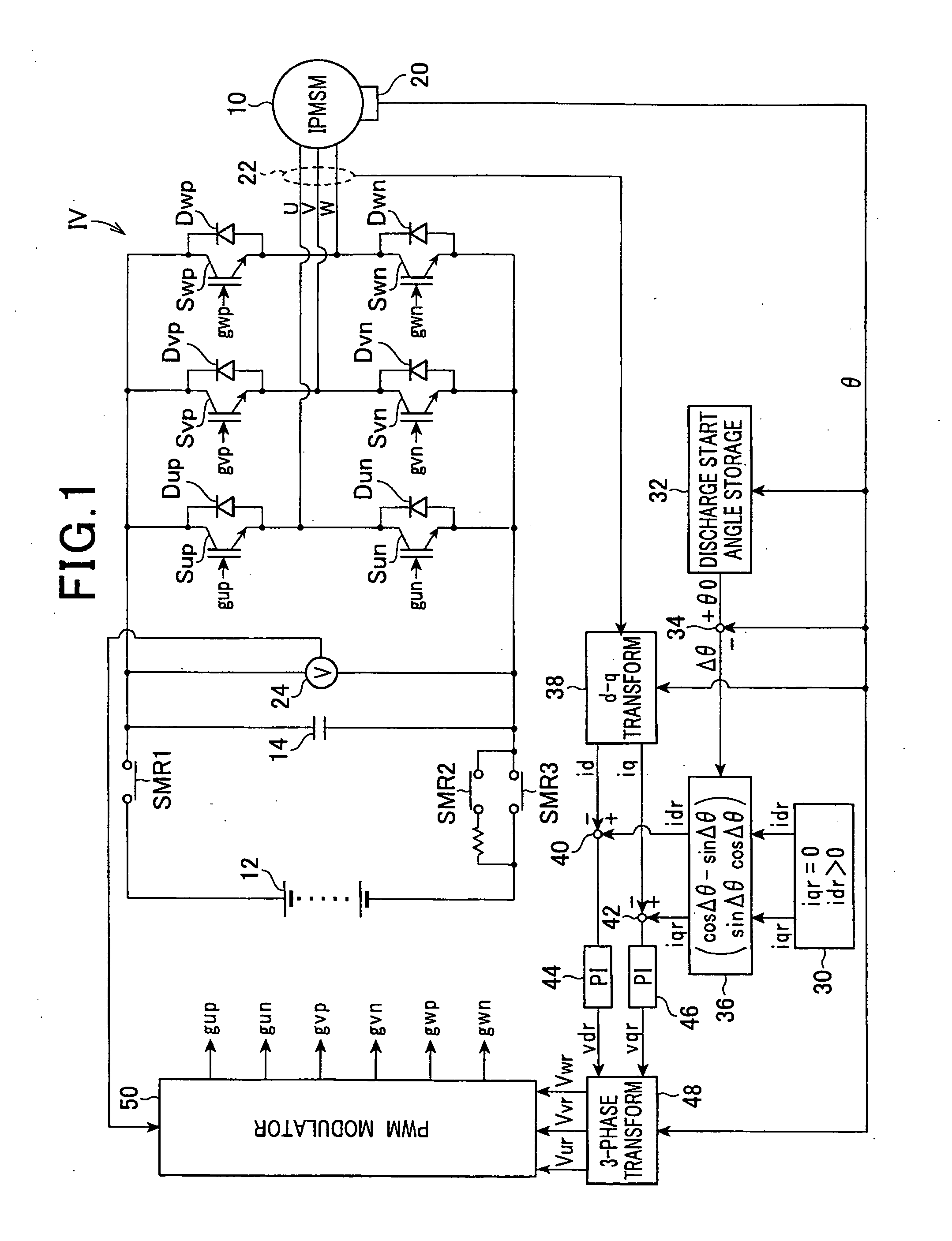
[0027]Referring to the drawings, wherein like reference numbers refer to like parts in several views, particularly to FIG. 1, there is shown a control apparatus for controlling an operation of a motor-generator 10 (i.e., an electric rotating machine) through an electric power conversion system according to the The motor-generator 10, as referred to herein, is installed in a hybrid vehicle.

[0028]The motor-generator 10 is a three-phase motor-generator and works as a main engine coupled to driven wheels of the vehicle. The motor-generator 10 is implemented by an interior permanent magnet synchronous motor (IPMSM) equipped with concentrated three-phase windings U, V, and W. The three-phase windings U, V, and W of the motor-generator 10 are, as can be seen from the drawing, connected to a high-voltage battery 12 (i.e., a secondary battery used as a dc power supply) through an inverter IV and relays SMR1, SMR2, and SMR3.

[0029]The inverter IV works as a dc / ac converter and is equipped wit...

second embodiment

[0052]The second embodiment will be described below.

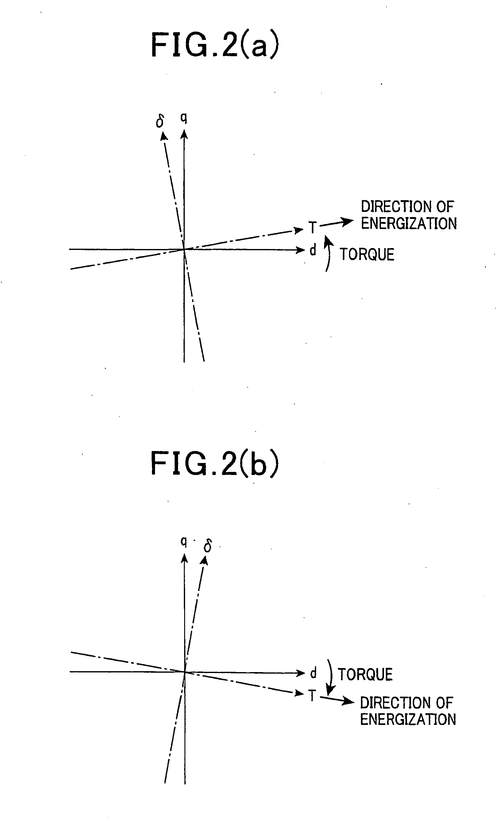
[0053]The motor-generator 10 is, as described above, equipped with the concentrated phase windings U, V, and W, so that great effects of space harmonics will appear. The relation between the torque T and the currents id and iq flowing through the motor-generator 10 may, thus, not conform to Eq. (1c), as described above, but depend upon the rotation angle θ. Consequently, when the command currents idr and iqr are provided in the same manner as in the first embodiment, it may cause the torque that is not zero (0) to be produced in the motor-generator 10 when an actual rotation angle of the motor-generator 10 agrees just with the start angle θ0.

[0054]In order to alleviate the above problem, the control apparatus of this embodiment works to determine the command currents idr and iqr as a function of the start angle θ0.

[0055]FIG. 4 illustrates the control apparatus of the second embodiment. The same reference numbers as employed in the ...

fourth embodiment

[0067]Each of the first to fourth embodiment may be modified as discussed below.

Command Voltage Fixing Circuit

[0068]Instead of a command voltage fixing circuit equipped with the discharge command voltage determining circuit 60, as illustrated in FIG. 5, which is separate from a command voltage determining circuit working to adjust the torque or speed of the motor-generator 10 to other than zero (0) in a normal control mode, the control apparatus of FIG. 1 may be designed to have the command voltage fixing circuit in which the start angle θ0, as stored in the discharge start angle storage 32, is inputted to the three-phase transformer 48, the outputs from the d-q transformer 38 are not updated, in other words, fixed, and the integrating controllers of the feedback controllers 44 and 46 are disenabled, in other words, integrating operations of the feedback controllers 44 and 46 are stopped not to update outputs therefrom. In this structure, when the motor-generator 10 is at the start ...


PUM


Abstract

A control apparatus for use with an electric power conversion system which is equipped with a dc/ac converter connected to an electric rotating machine and a capacitor joined to input terminals of the dc/ac converter. The control apparatus stores an angle of rotation (i.e., start angle θ0) of the electric rotating machine before start of control of energization of the electric rotating machine to discharge the capacitor and determines command currents idr and iqr which will result in zero (0) torque in the electric rotating machine. The control apparatus includes a command current correcting circuit which corrects the command currents idr and iqr by a difference between a current angle θ of rotation of the electric rotating machine and the start angle θ0, thereby avoiding constant rotation of the electric rotating machine when the capacitor is discharged.

Description

CROSS REFERENCE TO RELATED DOCUMENT[0001]The present application claims benefits of Japanese Patent Application No. 2010-41754 filed on Feb. 26, 2010 and Japanese Patent Application No, 2011-5611 filed on Jan. 14, 2011, disclosures of which are incorporated herein by reference.BACKGROUND[0002]1. Technical Field[0003]The present invention relates generally to a control apparatus for use with an electric power conversion system which is equipped with a dc / ac converter connected to an electric rotating machine and a capacitor joined to input terminals of the dc / ac converter, and more particularly to such a control apparatus designed to control an operation of the dc / ac converter so as to decrease the voltage charged in the capacitor below a given level.[0004]2. Background Art[0005]Japanese Patent First Publication No. 9-70196 discloses a control apparatus designed to control energization of a three-phase permanent-magnet electric motor so as to set a command current in a q-axis directi...

Claims


Application Information

Patent Timeline
Patent Type & Authority Applications(United States)
IPC IPC(8): H02P21/00H02P21/05H02P21/13H02P21/22H02P21/36H02P23/04H02P25/026H02P27/06H02P27/08
CPCH02P21/0003
Inventor TSUJI, HIROYAMORIOKA, TATSURUINAMURA, HIROSHIOOWADA, TAKAHUMI
Owner DENSO CORP
Why Eureka
Try Eureka