Magnetic resonance imaging system comprising a power supply unit adapted for providing direct current electrical power

a technology of magnetic resonance imaging and power supply unit, applied in the direction of magnetic variable regulation, measurement using nmr, instruments, etc., can solve the problems of inability to use, different countries or regions using different mains voltages, and large devices of transformers, so as to reduce the consumption of electrical power, reduce the cost, and reduce the effect of power consumption

Active Publication Date: 2011-09-01
KONINKLIJKE PHILIPS ELECTRONICS NV
View PDF19 Cites 63 Cited by
  • Summary
  • Abstract
  • Description
  • Claims
  • Application Information

AI Technical Summary

Benefits of technology

[0007]A standard voltage is distributed to the majority of the subunits. High power subunits such as the gradient amplifier or the RF amplifier can benefit from using a specialized power. A safer voltage can be chosen for the distribution of DC power, e.g. 40V. If necessary, each device can locally generate its own desired DC voltage via DC-DC conversion. DC to DC power conversion is a well-known, reliable compact technology.
[0032]In another embodiment, power bus is further adapted to transmit data between the power distribution means and the subunits. This has the advantage that power bus can be used as part of the control means for regulating the power to the subunits. The power bus can be adapted by adding a network cable such as a category 5 cable or optical fiber. The power bus can also be adapted by imposing a high frequency carrier onto one or more of the conductors used for transmitting electrical power. This has the advantage that no additional cables need to be added.

Problems solved by technology

A difficulty is that different countries or regions used different mains voltages.
Transformers are large devices, and cannot be used close to the magnet unless they are magnetically shielded.
The electromagnetic fields generated by the AC electrical power and transformers can interfere with the acquisition of MRI image data.
The power of all of these individual subunits is not managed efficiently.
All of these transformers are expensive and consumes valuable space in the hospital.
The wiring for MRI systems can become quite complicated and the voltages used are hazardous.

Method used


Image

  • Magnetic resonance imaging system comprising a power supply unit adapted for providing direct current electrical power
  • Magnetic resonance imaging system comprising a power supply unit adapted for providing direct current electrical power
  • Magnetic resonance imaging system comprising a power supply unit adapted for providing direct current electrical power

Examples


Embodiment Construction

[0038]Like numbered elements in these figures are either identical elements or perform the same function. Elements which have been discussed previously will not necessarily be discussed in later figures if the function is identical.

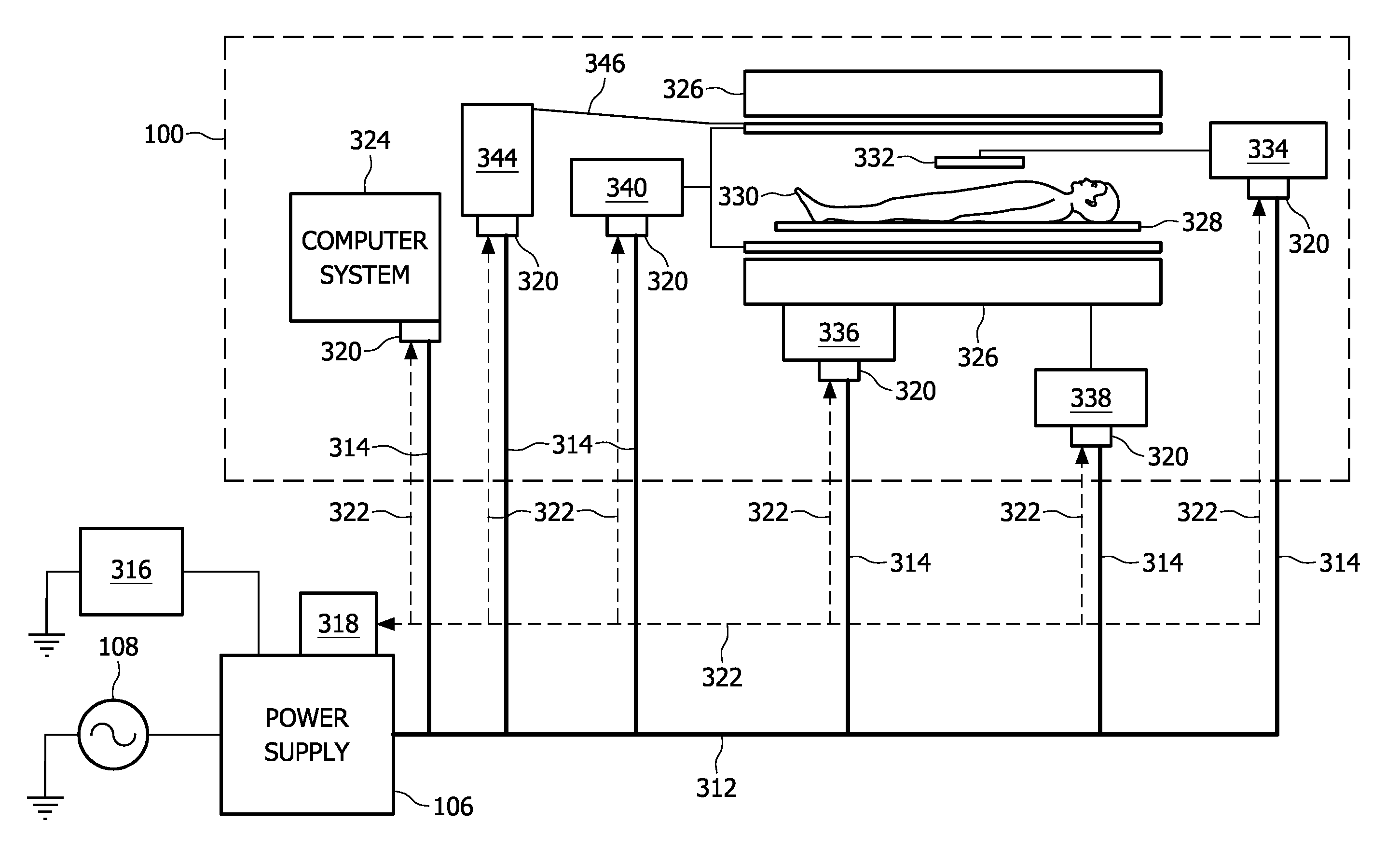
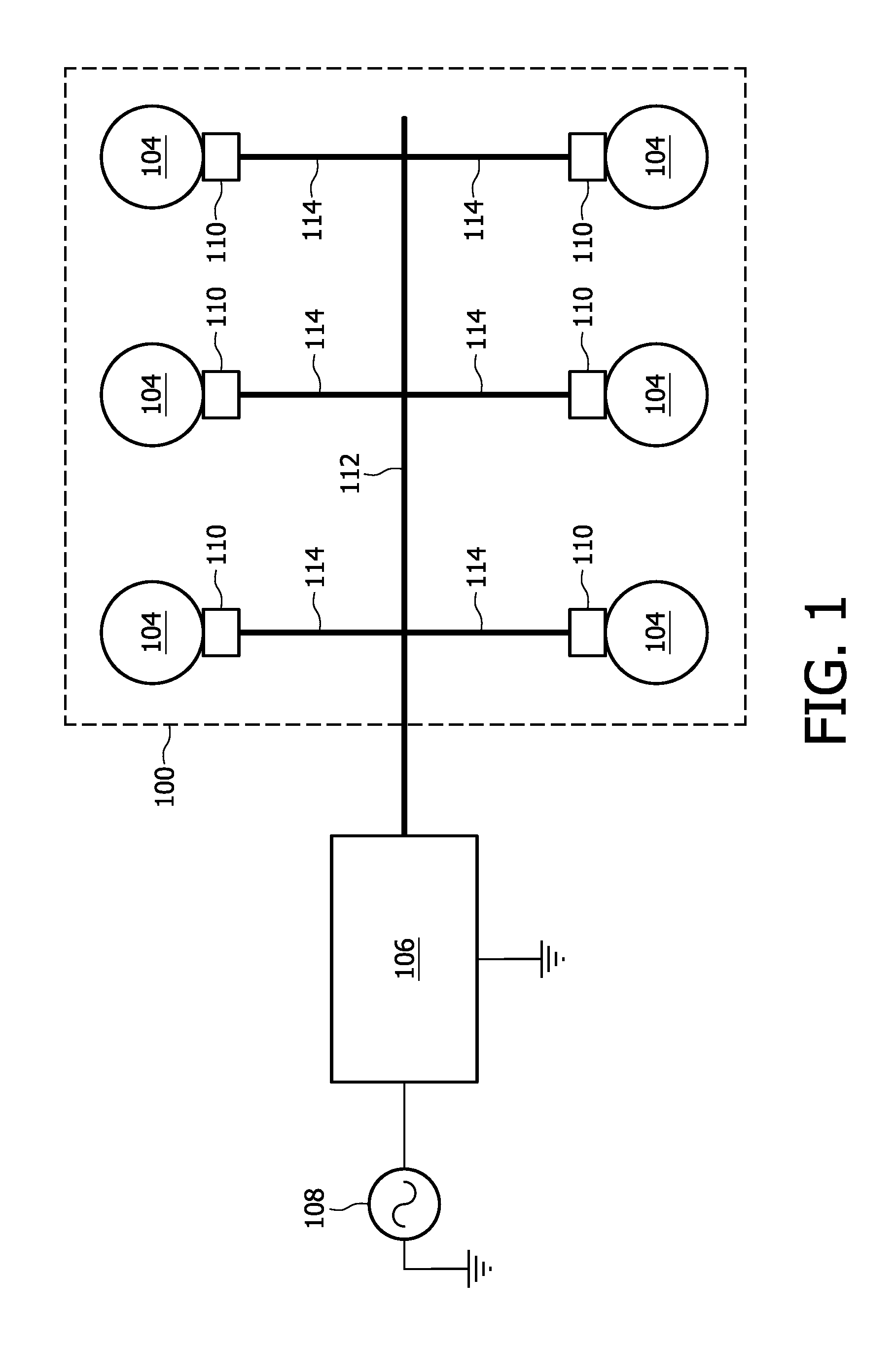
[0039]FIG. 1 shows an embodiment of an MRI system with a power bus 112 which extends into the data acquisition means 100 and provides a way of connecting the subunits 104 to the electrical power bus 112. This is an idealized figure which is intended to show the layout of the electrical system. There is an AC electrical mains 108 which provides AC electrical power. This is connected to the power supply 106. The power supply is then connected to the power bus 112 and the power bus extends into the vicinity of the data acquisition means 100. The data acquisition means 100 has electrical connections 114 between the power bus 112 and every subunit 104. There is one of these connections 114 for every subunit 104. Subunits 104 are connected to a control means 11...


PUM


Abstract

A MRI system for acquiring MRI image data comprising a data acquisition means comprising a plurality of subunits for acquiring MRI image data, a power distribution means for providing the means for acquiring MRI image data with electrical power, the power distribution means comprising: a power supply unit adapted for providing direct current electrical power from an alternating current electrical mains, a power bus adapted for supplying the subunits with the direct current electrical power, control means for controlling the supply of direct current electrical power by the power bus to the subunits.

Description

FIELD OF THE INVENTION[0001]The invention relates to magnetic resonance imaging systems and in particular to the distribution of electrical power in magnetic resonance imaging systems.BACKGROUND OF THE INVENTION[0002]A static magnetic field is used by Magnetic Resonance Imaging (MRI) scanners to align the nuclear spins of atoms as part of the procedure for producing images within the body of a patient. During an MRI scan, Radio Frequency (RF) pulses generated by a transmitter coil cause perturbations to the local magnetic field, and RF signals emitted by the nuclear spins are detected by a receiver coil. These RF signals are used to construct the MRI images. These coils can also be referred to as antennas. Further, the transmitter and receiver coils can also be integrated into a single transceiver coil that performs both functions. It is understood that the use of the term transceiver coil also refers to systems where separate transmitter and receiver coils are used.[0003]An MRI sys...

Claims


Application Information

Patent Timeline
Patent Type & Authority Applications(United States)
IPC IPC(8): G01R33/44G01R33/28H02J9/06
CPCG01R33/3852G01R33/28
Inventor HAM, CORNELIS LEONARDUS GERARDUS
Owner KONINKLIJKE PHILIPS ELECTRONICS NV
Why Eureka
Try Eureka