Backlight unit

a backlight unit and backlight technology, applied in the field of backlight units, can solve the problems of consuming a large amount of power, pcb boards are expensive, drivers, etc., and achieve the effect of simplifying the structure of the uni

Active Publication Date: 2011-09-01
SUZHOU LEKIN SEMICON CO LTD
View PDF21 Cites 101 Cited by
  • Summary
  • Abstract
  • Description
  • Claims
  • Application Information

AI Technical Summary

Benefits of technology

An object of the present invention is to provide a backlight unit in which a light source module is positioned between two refle

Problems solved by technology

However, since the backlight unit of CCFL has power always applied to the CCFL, the backlight unit has drawbacks in that a substantial amount of power is consumed, a color reproduction ratio is about 70% level compared to a CRT, and mercury contained in the CCFL causes environmental contamination.
Moreover, it is a featu

Method used


Image

  • Backlight unit
  • Backlight unit
  • Backlight unit

Examples


Embodiment Construction

Reference will now be made in detail to the specific embodiments of the present invention, examples of which are illustrated in the accompanying drawings. Wherever possible, the same reference numbers will be used throughout the drawings to refer to the same or like parts.

It is required to understand that, in a description that a layer (a film), a region, a pattern, or a structure is formed “on” or “under” a substrate, a layer (a film) a region, a pad, or pattern, the “on”, or “under” implies that the layer (the film), the region, the pattern, or the structure is formed directly or indirectly. And, reference on the “on” or “under” is the drawing.

A thickness or a size of a layer shown in a drawing is exaggerated, omitted or shown schematically for convenience or clarity of description. And, a size of an element is not shown to scale, perfectly.

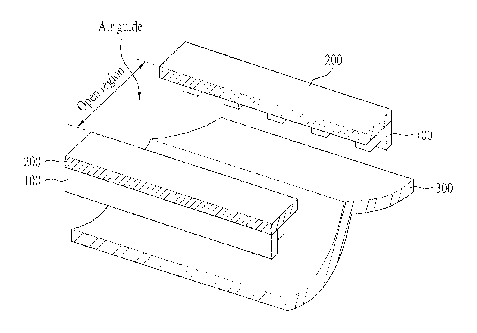
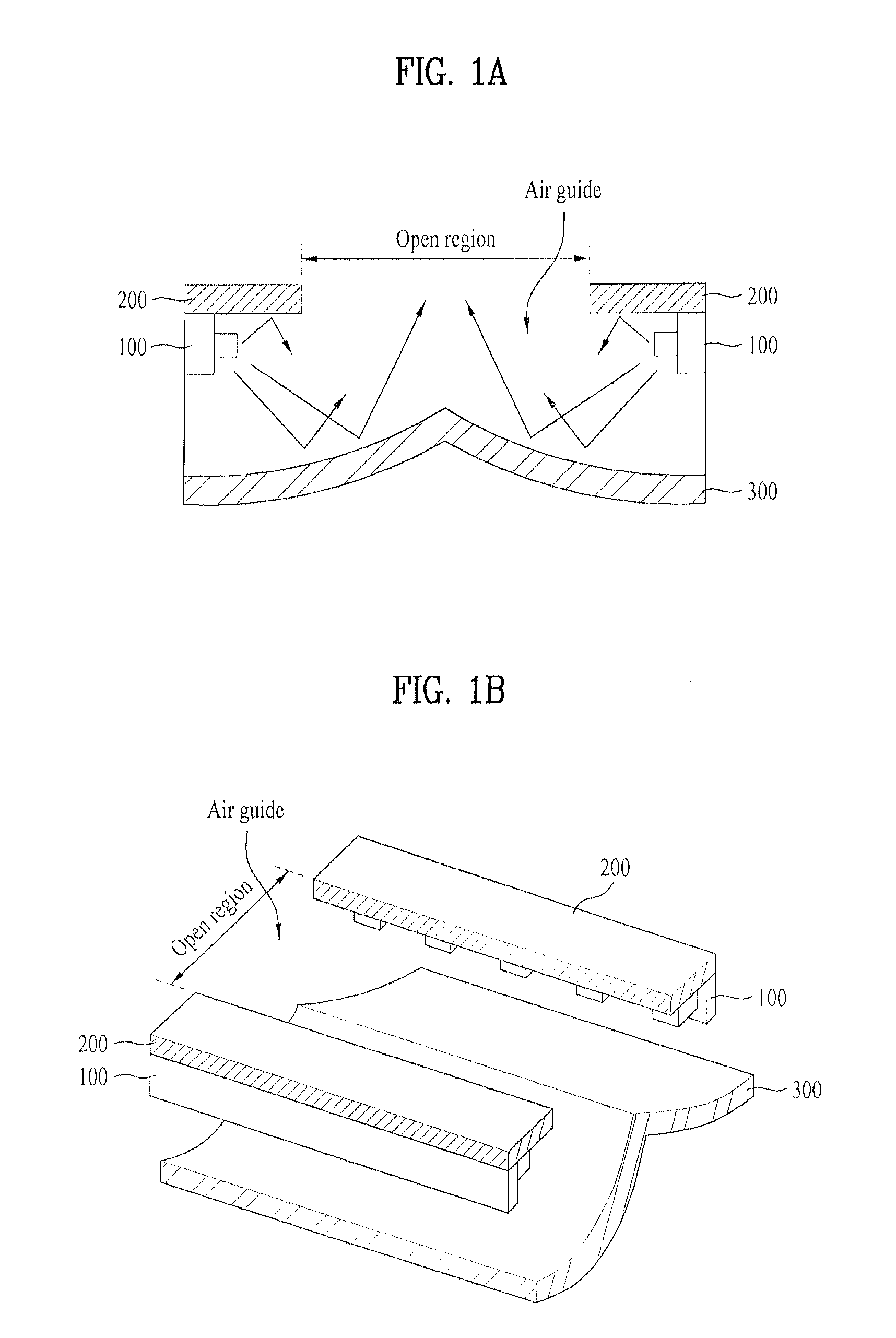
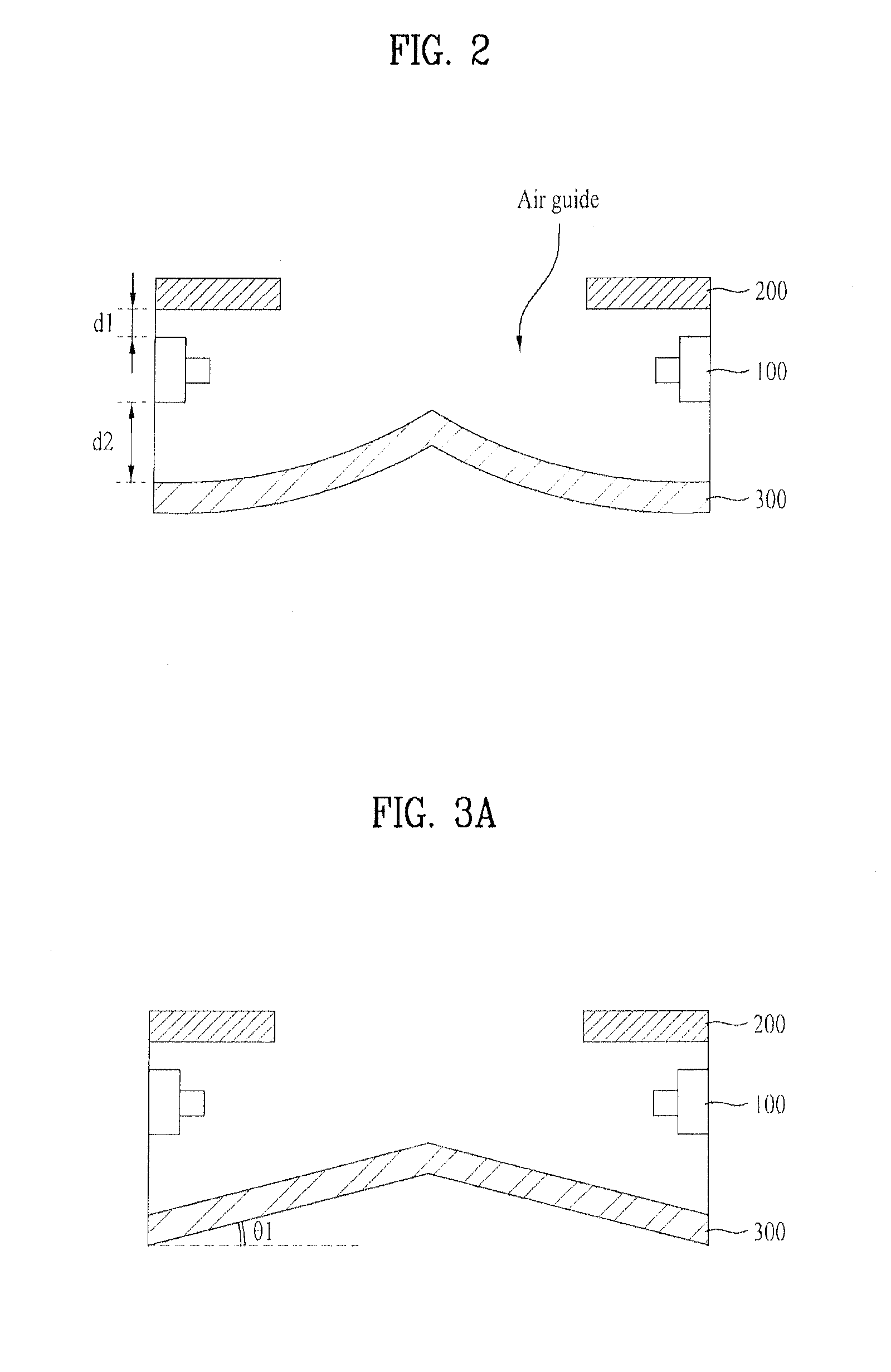
FIGS. 1A and 1B illustrate schematic views each showing a two edge type backlight unit in accordance with a preferred embodiment of the presen...


PUM


Abstract

The present invention relates to a backlight unit having a reflective portion, including a light source module for emitting a light, a first reflective portion arranged spaced a first distance away from one side of the light source module to have an open region, and a second reflective portion arranged spaced a second distance which is greater than the first distance away from the other side of the light source module to have at least a portion with a sloped surface for reflecting the light toward the open region of the first reflective portion.

Description

CROSS REFERENCE TO RELATED APPLICATIONThis application claims the benefit of the Patent Korean Application Nos. 10-2010-0123704, filed on Dec. 6, 2010 and 10-2011-0000877 filed on Jan. 5, 2011, which are hereby incorporated by reference as if fully set forth herein.BACKGROUND OF THE DISCLOSURE1. Field of the DisclosureThe present invention relates to a backlight unit having reflective portions.2. Discussion of the Related ArtIn general, as a typical large sized display device, there are LCD (Liquid Crystal Display Device), PDP (Plasma Display Panel) and so on.Different from a spontaneous light emission type PDP, since the LCD has no light emission device for itself, the LCD requires a separate backlight unit, essentially.In the backlight unit of the LCD, there are an edge light type backlight unit, and a direct light type backlight unit depending on positions of a light source of the backlight unit, wherein, since the edge light type has the light source arranged at a left or right ...

Claims


Application Information

Patent Timeline
IPC IPC(8): G02F1/13357F21V7/00
CPCG02B6/0046G02B6/0053F21V7/0066G09F13/14F21K9/50G02B6/0096F21K9/60
Inventor KO, SE JIN
Owner SUZHOU LEKIN SEMICON CO LTD
Why Eureka
Try Eureka