Device for determining the stability of a knee joint

a technology the knee joint, which is applied in the field of devices for can solve the problems of purely dependent examination, knee joint instability, and take tensile forces, and achieve the effect of determining the stability of the knee joint, simple structure and simplifying the handling of the devi

Inactive Publication Date: 2011-09-01
BORT
View PDF10 Cites 74 Cited by
  • Summary
  • Abstract
  • Description
  • Claims
  • Application Information

AI Technical Summary

Benefits of technology

[0024]In the case of the device for determining the stability of a knee joint according to the present invention, it is possible to make a statement regarding the stability of the knee joint with the aid of the merely one measuring sensor, which is attached via a fastening device to a lower leg associated with the knee joint, and of the processing device for processing the measured values of the measuring sensor. The handling of the device is substantially simplified by this simple structure with only a few components. In particular, the therapist does not have to operate any element of the device while carrying out a diagnostic method and thus has both hands free for the diagnostic method.
[0043]According to one embodiment, the fastening device comprises at least one holding shell with fastening means for fastening the holding shell to the lower leg. For an accurate determination of the acceleration or the distance between the contactless measuring sensor and the reference point, it is crucially important for the measuring sensor to be moved together with the lower leg. For this reason, it is necessary for the measuring sensor to be firmly connected to the lower leg and to be unable to slip, tilt or otherwise move in relation to the lower leg. The holding shell ensures a high tilting and rotational stability. Furthermore, the holding shell can be matched to the anatomy of the human lower leg, it being possible for the holding shell to be fastened to the lower leg with the aid of fastening means. The fastening means can be a crepe fastener. The fastening means can also comprise a hook attached to a flexible strip, which can be hung onto an eye element on the medial side of the tibia. The holding shell can be designed in such a way that it is attachable both to the left and right lower leg.

Problems solved by technology

Like all ligaments in the human body, however, they can only take tensile forces.
Since the posterior is cruciate ligament cannot take compressive forces, the knee joint becomes unstable.
However, Lachmann, anterior drawer and pivot-shift tests carried out by a therapist have the disadvantage that the results of the examination depend purely subjectively on the assessment and experience of the therapist.
However, this method has the disadvantage that the patient is exposed to considerable radiation.
However, for routine diagnostics in small surgical outpatient departments or practices, magnetic resonance tomographs are generally too expensive and require considerable installation space and technical resources.
The use of such devices is, however, awkward in some cases, since the devices have to be fastened to the patient's leg at more than one place.
Moreover, the devices are of a certain size, making them difficult to handle.
Also, the accuracy of the measurement results is often not sufficient.
Furthermore, with known arthrometers it is only possible to carry out the Lachmann test.
Determination of the rotational stability of the knee joint cannot be performed with such known devices.
This is due in particular to the fact that the rotational stability of the knee joint can be produced only to a limited degree with older operating techniques.
Since the therapist has to grasp or move the lower leg or the thigh when carrying out the diagnostic methods, a wired connection between the measuring sensor and the processing device would make it more difficult to carry out the diagnostic methods.

Method used


Image

  • Device for determining the stability of a knee joint
  • Device for determining the stability of a knee joint
  • Device for determining the stability of a knee joint

Examples


Embodiment Construction

[0056]Exemplary embodiments of the present invention when carrying out the Lachmann or pivot-shift test are explained below. However, the present invention is not restricted to a use in the Lachmann or pivot-shift test. In principle, the present invention can be used in any diagnostic method in which the lower leg and / or the thigh is moved.

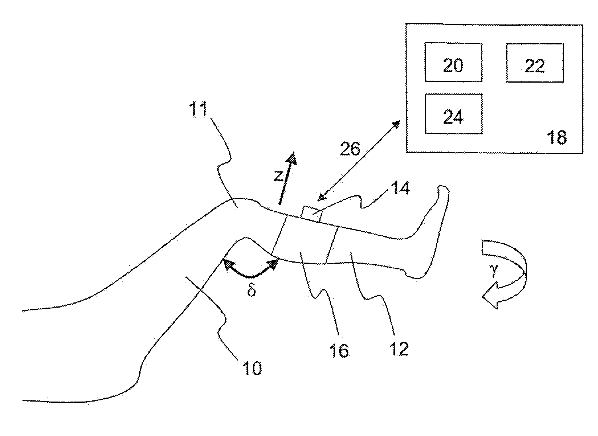
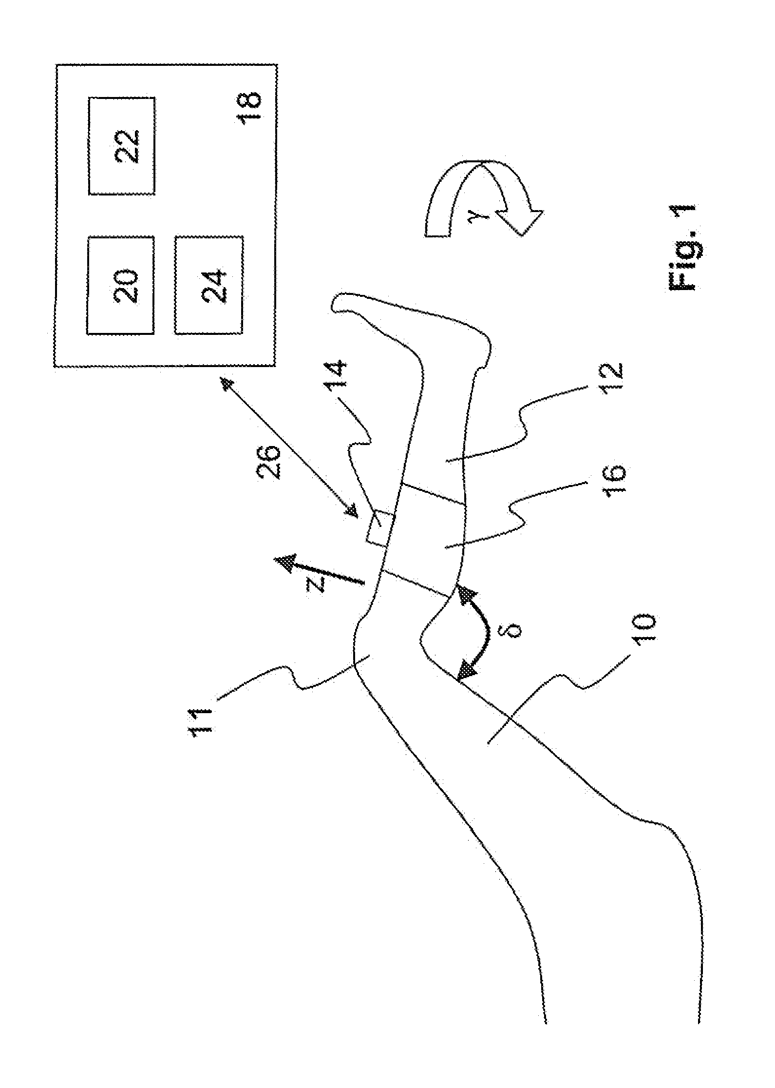
[0057]FIG. 1 shows a schematic illustration of a human leg with a device according to the invention for determining the stability of a knee joint. Both the translational stability and the rotational stability of a knee joint can be determined with the device shown.

[0058]The leg comprises a thigh 10, a knee joint 11 to be diagnosed and a lower leg 12.

[0059]An inertial sensor 14 is fastened to the lower leg 12 with the aid of a fastening device 16. Furthermore, a processing device 18 for processing the measured values of the inertial sensor 14 is provided. The processing device 18 comprises a display 20, a storage device 22 and processing logic 24.

[...


PUM


Abstract

The invention relates to a device for determining the stability of a knee joint. The device comprises includes a measuring sensor (14), which can be attached via a fastening device (16) to a lower leg (12) associated with the knee joint (11). The measuring sensor (14) is designed to measure an acceleration in at least one direction (z) during a movement of the lower leg (12). Furthermore, a processing device (18) is provided for processing measured values of the measuring sensor (14) in order to infer the stability of the knee joint (11) from the processed measured values.

Description

BACKGROUND[0001]1. Technical Field[0002]The invention relates to a device for determining the stability of a knee joint with at least one contactless measuring sensor.[0003]2. Description of Related Art[0004]The cruciate ligaments of the human knee joint stabilise the femur (thigh bone) with respect to the tibia (shin bone). Like all ligaments in the human body, however, they can only take tensile forces. To stabilise the knee joint, therefore, there are two cruciate ligaments which run in opposite directions to one another.[0005]If in the event of a cruciate ligament rupture (cruciate ligament tear), the anterior cruciate ligament, for example, is severed, it can no longer take tensile forces. Since the posterior is cruciate ligament cannot take compressive forces, the knee joint becomes unstable. Consequently, after such a cruciate ligament rupture, it is possible for the shin bone to move, through tension, further in the “forward” direction with regard to the thigh than is possib...

Claims


Application Information

Patent Timeline
Patent Type & Authority Applications(United States)
IPC IPC(8): A61B5/11
CPCA61B5/1071A61B5/11A61B5/1121A61B5/6831A61B5/4528A61B5/6828A61B2562/0219A61B5/1124
Inventor BOOS, RONALDMARQUARDT, GERHARDSCHNEIDER, URSBORT, WOLFGANG
Owner BORT
Why Eureka
Try Eureka