Inductance coil and laser-cutting manufacturing method of inductance coil

A technology of inductance coil and laser cutting, which is applied in the direction of transformer/inductor coil/winding/connection, manufacturing tools, welding equipment, etc., and can solve the problems of open circuit failure, influence, and complicated manufacturing process at the lead-out welding place

Inactive Publication Date: 2013-09-04
SHENZHEN SUNLORD ELECTRONICS
View PDF7 Cites 27 Cited by
  • Summary
  • Abstract
  • Description
  • Claims
  • Application Information

AI Technical Summary

Problems solved by technology

The two lead-out ends of the coil are respectively welded to the two terminals. After powder filling molding, the two terminals are bent as terminal electrodes, which cannot realize mass-automatic production, and the production efficiency is low; It is easy to be deformed and shifted; because the internal coil and the terminal electrode are not integrated, they are connected by hot-press welding, which will inevitably lead to open circuit failure during product manufacturing or customer use; because the wire adopts the traditional enameled film insulation process, the insulation layer Low strength, during the molding process, the extrusion of powder particles will cause damage to the insulating film, so there is a risk of short circuit
[0003] Another example is the "Surface Mount Inductor Manufacturing Method and Surface Mount Inductor" disclosed in US Patent US20100259353A1. The inside of the inductor is a flat enameled wire wound coil, the coil is placed on the semi-solidified magnetic core, and the two leads of the coil are attached to the magnetic core. The outer side is covered with a prepreg magnetic sheet, hot-pressed, and then the end is dipped in low-temperature conductive glue and electroplated to form a terminal electrode. There are also problems encountered in the Chinese patent CN101499360A: the coil is a single stand, and the prepreg is placed The process of magnetic core and prepreg is complicated, and it is difficult to realize automatic production; there are also hidden dangers in the design of terminal electrodes. The accuracy of coil placement will directly affect the effect of the lead-out end against the outside of the magnetic core, the horizontal position and rotation angle of the coil placement and the lead-out If the angle of the terminal is slightly deviated, it is difficult to control the exposed area of ​​the terminal and the size of the product, which will lead to the hidden danger of open circuit failure and the hidden danger of product size out-of-tolerance; because the magnet is made of iron-based metal soft magnetic, the conductivity is large, and the terminal electroplating process is also difficult. control, there will be hidden dangers such as climbing plating and magnet corrosion; because the low-temperature silver glue and the lead-out end are bonded through the curing of the resin in the silver glue to achieve the bonding effect, the adhesion is low, which will cause the patch to fall off and fail during the use of the client Hidden danger
The wound coils are sequentially welded on the frame with feet, which facilitates the automatic feeding of the powder molding process. However, coil winding and foot frame welding still consume a large amount of production cycle. Like the above two patents, there are coil deformation deviations. The hidden danger of open circuit failure at the soldering point of the position and the terminal, and the hidden danger of short circuit failure caused by the damage of the enamelled film during the molding process
[0005] To sum up, the traditional one-piece inductance process using enamelled copper wire to wind the coil has the defects of difficult coil positioning, large open and short circuit risks, complex manufacturing process, long production cycle, high cost, and difficulty in automation

Method used


Image

  • Inductance coil and laser-cutting manufacturing method of inductance coil
  • Inductance coil and laser-cutting manufacturing method of inductance coil
  • Inductance coil and laser-cutting manufacturing method of inductance coil

Examples


Embodiment Construction

[0096] The present invention will be described below in combination with specific embodiments and with reference to the accompanying drawings.

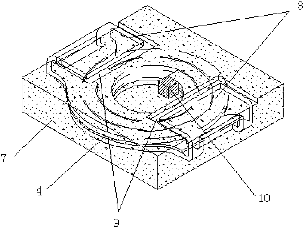
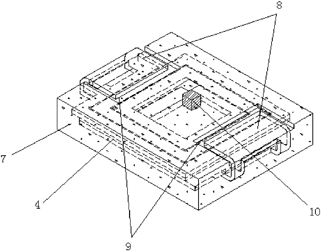
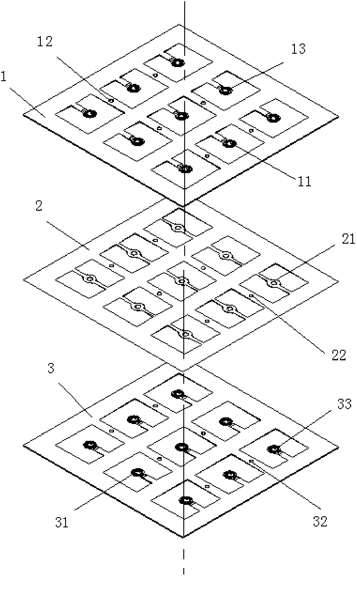
[0097] a kind of like Figure 1-12 The shown inductance coil includes an upper copper foil coil 11 and a lower copper foil coil 31 with an insulating coating on the outer surface for insulation treatment, and a high temperature resistant organic film arranged between the layers of the upper copper foil coil 11 and the lower copper foil coil 31 2, and the magnetic material layer 7 wrapped around the upper copper foil coil 11 and the lower copper foil coil 31, the passing area of ​​the upper copper foil coil 11 and the lower copper foil coil 31 is 0.0010mm 2 The upper coil welding preset connection point 13 and the lower coil welding preset connection point 33 are connected by ultrasonic welding to ensure the reliability of welding. figure 1 , 2 The welding area 10 in is the connection point of the upper copper foil coil 11 and the lo...


PUM

PropertyMeasurementUnit
thicknessaaaaaaaaaa
thicknessaaaaaaaaaa
thicknessaaaaaaaaaa

Abstract

The invention provides an inductance coil and a laser-cutting manufacturing method of the inductance coil. The inductance coil comprises an upper copper foil coil, a lower copper foil coil, a heat-resistant organic thin film and magnetic material layers, wherein the outer surface of the upper copper foil coil and the outer surface of the lower copper foil coil are provided with insulating coatings for insulating treatment, the heat-resistant organic thin film is arranged between the upper copper foil coil and the lower copper foil coil, and the magnetic material layers wrap the periphery of the upper copper foil coil and the periphery of the lower copper foil coil. Coil patterns of the upper copper foil coil and the lower copper foil coil are formed through cutting by a laser light source. The insulating coatings are heat-resistant coatings. The magnetic material layers are formed through compression molding, and a magnetic material is iron metal alloy soft magnetic powder. The laser-cutting manufacturing method comprises laser cutting on the upper copper foil coil, the lower copper foil coil and the heat-resistant organic thin film. The inductance coil is formed by copper foil in a laser-cutting mode, parameters including line width, thickness, distance between lines, coil center pillars and the like can be adjusted to form the coil patterns on normal positions, and target characteristic specifications can be designed quite easily. The inductance coil and the laser-cutting manufacturing method of the inductance coil overcome the shortcomings that an existing inductance coil is difficult to fix and loses efficacy in an open circuit and a short circuit, and end electrodes are difficult to design, and better accord with the development tendency that a power inductor is small, thin and low in cost.

Description

technical field [0001] The invention relates to a coil, in particular to an inductance coil and a laser cutting manufacturing method thereof. Background technique [0002] The existing traditional one-piece inductor coil manufacturing methods include copper metallurgy copper wire, copper wire surface resin insulation treatment, enameled copper wire winding coil, which greatly restricts the production efficiency. For example, "Inductor and Manufacturing Method thereof" disclosed in Chinese patent CN101499360A, the inductor has a magnet with a predetermined shape and a coil embedded in the magnet. winding portion; two lead-out portions respectively provided on each end side of the winding portion; terminal portions continuously arranged on the end portion side of the lead-out portion and formed to have a width wider than the lead-out portion, each lead-out portion and each terminal The boundary of each terminal part is located in the magnet, and a part of each terminal part i...

Claims


Application Information

Patent Timeline
Patent Type & Authority Applications(China)
IPC IPC(8): H01F27/28H01F27/32B23K28/02
Inventor 夏胜程李有云蒋中立
Owner SHENZHEN SUNLORD ELECTRONICS
Why Eureka
Try Eureka