
Vacuum cleaning head

a vacuum cleaning and head technology, applied in the direction of mechanical suction control, suction nozzle, suction handle, etc., can solve the problem of inconvenient button pressing for users

Inactive Publication Date: 2011-09-08
DYSON TECH LTD
View PDF6 Cites 15 Cited by
  • Summary
  • Abstract
  • Description
  • Claims
  • Application Information

AI Technical Summary

Benefits of technology

[0013]The interior volume of the pressure chamber may be connected to an airflow path within the cleaning head, an airflow path extending from the cleaning head to the main body of a vacuum cleaning appliance to which the cleaning head is attached, or to an airflow path within the main body of the vacuum cleaning appliance. This can enable the air pressure within the pressure chamber, and therefore the force acting on the second chamber section, to be varied by the user through opening a valve to admit air into the chosen airflow path to which the pressure chamber is connected. Where the airflow path passes through the cleaning head, the valve may be located on a housing of the cleaning head. Where the air flow path extends from the cleaning head to the main body, the valve may be located on a wand of a wand and hose assembly for connecting the cleaning head to the main body, preferably in the vicinity of the handle of the wand. This can enable the user to vary the air pressure within the pressure chamber using a hand which is currently holding the wand, making the cleaner head easier to use.
[0014]When the control mechanism is in its first state, the control mechanism prevents the second chamber section from moving to its second position relative to the first chamber section, which may correspond to a fully contracted configuration of the pressure chamber. To move the control mechanism to its second state, the user may vary the air pressure within the pressure chamber, for example through opening an aforementioned valve, to decrease the pressure differential across the second chamber section. The second chamber section is preferably biased away from the first chamber section so that the second chamber section can move away from the third position intermediate the first and second positions, preferably towards the first position, in response to the reduction in the pressure differential. The control mechanism is arranged to change to the second state in response to this movement of the second chamber section away from the first chamber section so that the second chamber section can move to the second position when the valve is closed. Thus, by sequentially opening varying the air pressure within the pressure chamber, the user can toggle the control mechanism between its first and second states to vary the configuration of the pressure chamber. The change in the configuration of the pressure chamber can vary, for example, the state or position of an agitator for agitating dirt from a surface to be treated, a speed of rotation of such an agitator, or the relative positions of two other parts of the cleaning head.
[0015]The control mechanism is preferably arranged to adopt the first state when there is substantially no pressure difference across the second chamber section, for example when the vacuum cleaning appliance is switched off so that there is no air flow along the airflow path. As a result, the cleaning head will be in the same configuration each time the vacuum cleaning appliance is switched on, for example with an agitator in a default one of an active and an inactive state, to provide certainty for the user.
[0018]The pressure chamber may comprise two springs for urging the pressure chamber towards its expanded configuration. The first spring may be arranged to control the switching of the control mechanism between its first and second states, whereas the second spring may be arranged to urge the control mechanism into its first state when the pressure difference between the interior volume and the ambient air decreases to zero. For example, the pressure chamber may comprise an intermediary member located between the first and second chamber sections, a first spring for biasing the intermediary member away from the first chamber section, and a second spring for biasing the second chamber section away from the intermediary member. The control mechanism may extend about the intermediary member. The control mechanism may conveniently be provided with a stop for restricting the movement of the intermediary member away from the first chamber section under the action of the first spring.

Problems solved by technology

Furthermore, the depression of the button can be inconvenient for the user.

Method used


Image

  • Vacuum cleaning head
  • Vacuum cleaning head
  • Vacuum cleaning head

Examples


Embodiment Construction

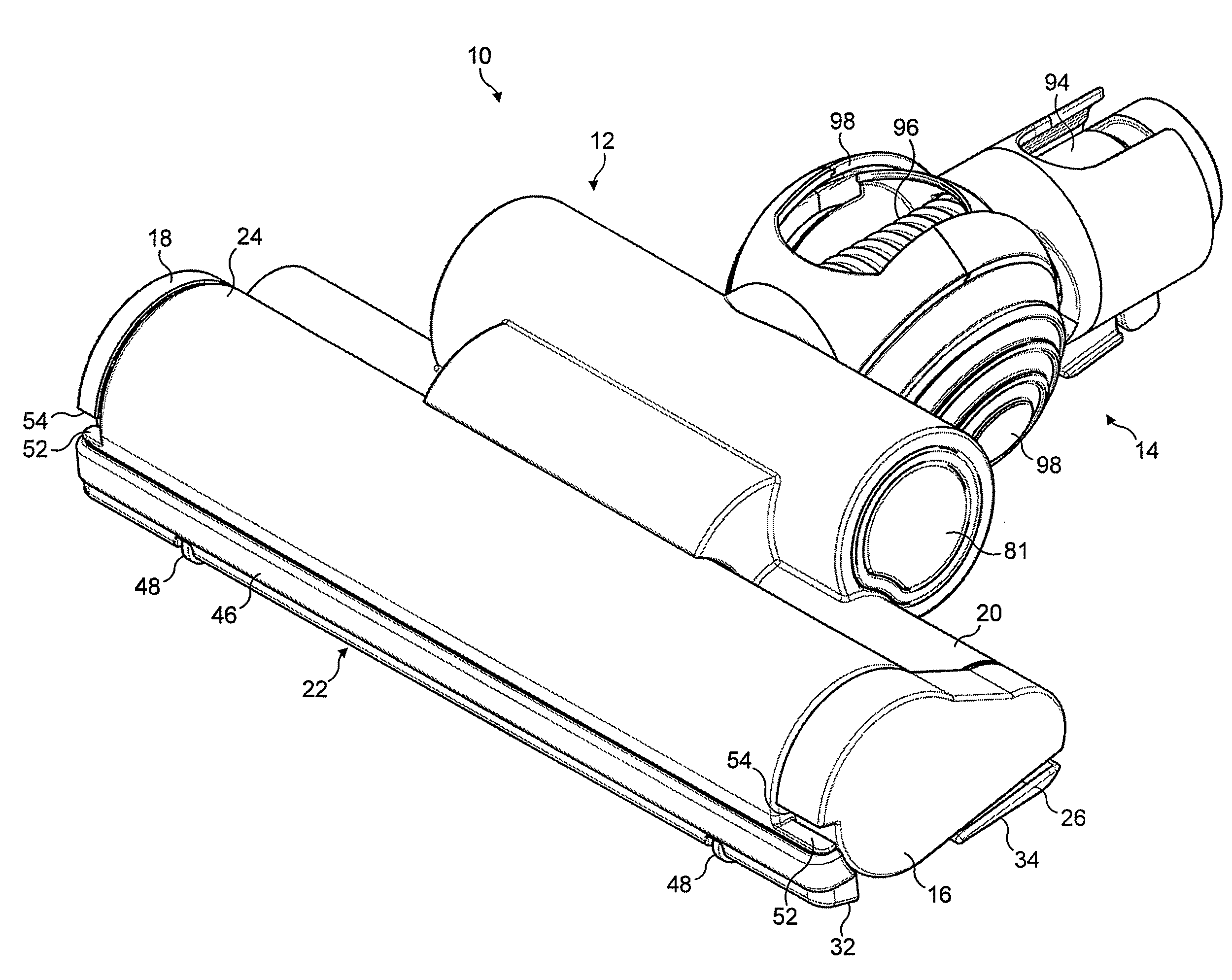
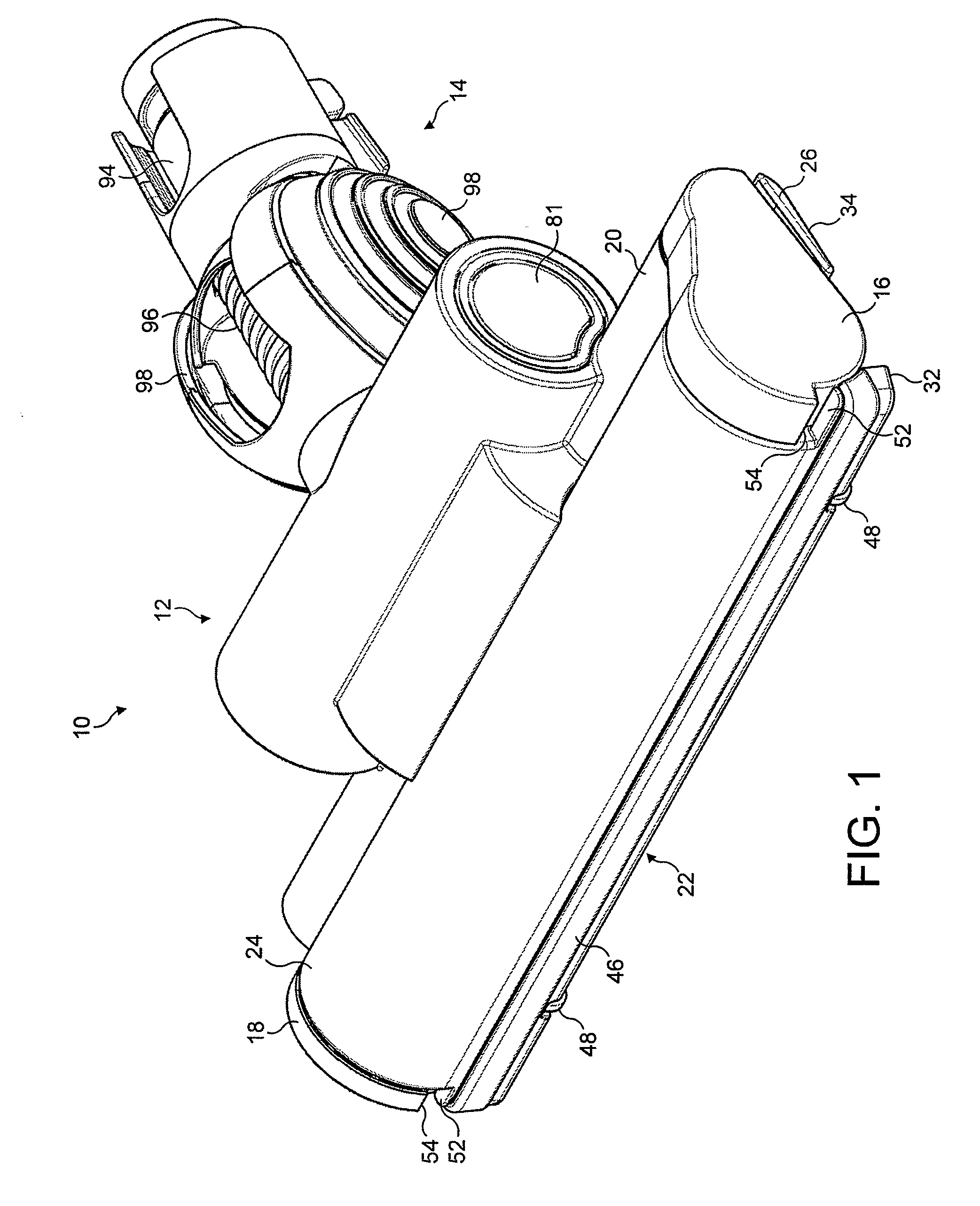
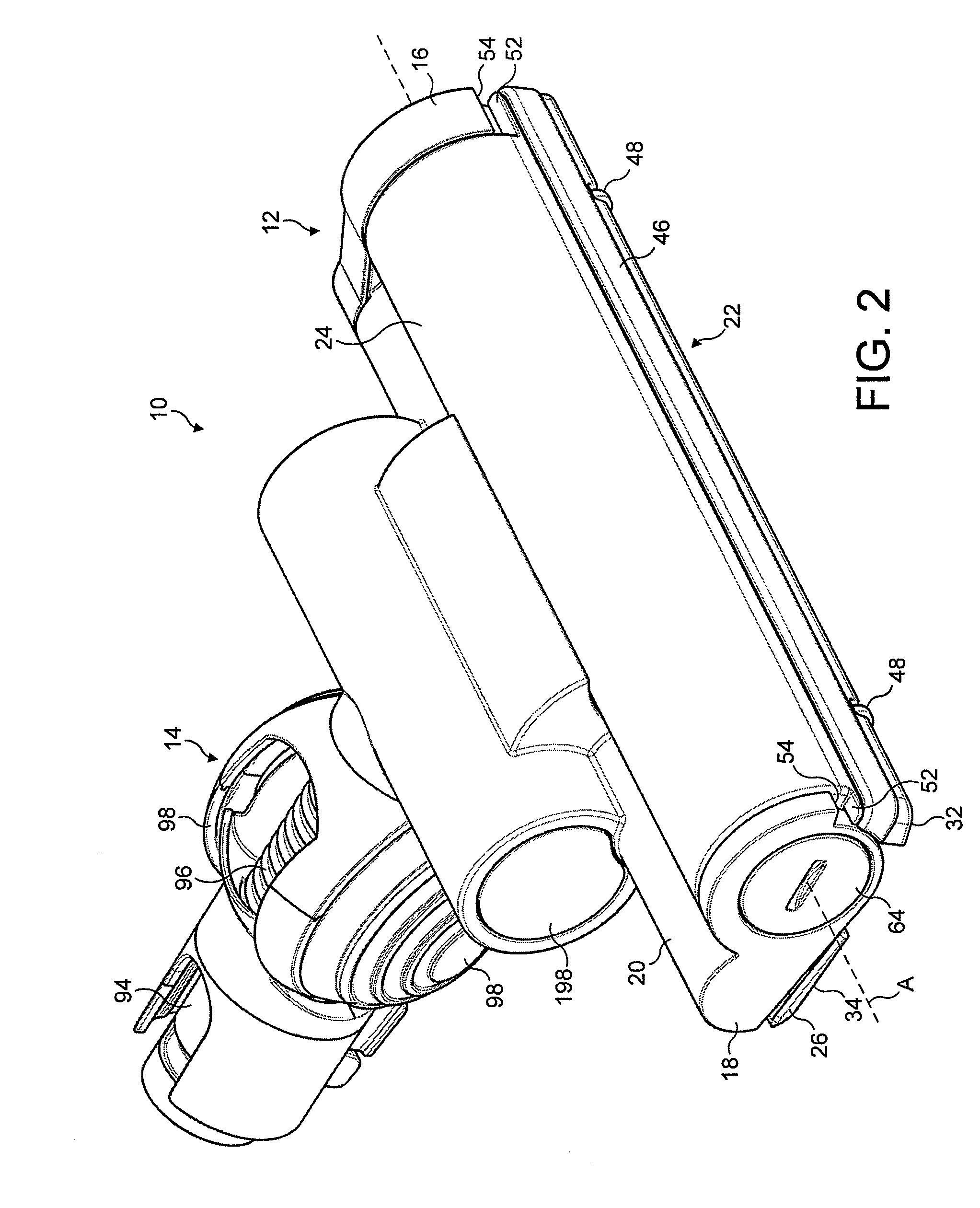
[0053]FIGS. 1 to 4 illustrate an embodiment of a floor tool 10 for a vacuum cleaning appliance. In this embodiment, the floor tool 10 is arranged to be connectable to a wand or hose of a cylinder vacuum cleaning appliance. The floor tool 10 comprises a main body 12 and a conduit 14 connected to the body 12. The main body 12 comprises substantially parallel side walls 16, 18 extending forwardly from opposite ends of a rear section 20 of the main body 12, and a moveable section 22 located between the side walls 16, 18 of the main body 12. In this embodiment the moveable section 22 is rotatably connected to the main body 12 for rotation about an axis A which extends generally orthogonally between the side walls 16, 18 of the main body 12.

[0054]The moveable section 22 comprises a curved upper wall 24, a lower plate, or sole plate 26, and two side walls 28, 30 which connect the sole plate 26 to the upper wall 24. The side walls 28, 30 are located between the side walls 16, 18 of the main...


PUM


Abstract

A vacuum cleaning head includes a pressure chamber having a first chamber section and a second chamber section which is moveable relative to the first chamber section in response to a pressure differential thereacross from a first position to a second position, and a control mechanism located within the pressure chamber. The control mechanism has a first state for inhibiting the movement of the second chamber section in response to said pressure differential beyond a third position intermediate the first and second positions, and a second state for allowing the second chamber section to move in response to said pressure differential to the second position. The control mechanism is arranged to change between the first and second states in response to a movement of the second chamber section from the third position. This can allow the pressure chamber to toggle between different configurations through varying the pressure differential across the second chamber section, for example to raise or lower part of the cleaner head, or to selectively activate or deactivate an agitator.

Description

REFERENCE TO RELATED APPLICATIONS[0001]This application claims the priority of United Kingdom Application No. 1003603.6, filed 4 Mar. 2010, and the United Kingdom Application No. 1101944.5, filed 4 Feb. 2011, the entire contents of which are incorporated herein by reference.FIELD OF THE INVENTION[0002]The present invention relates to a vacuum cleaning head which can be used with, or form part of, a vacuum cleaning appliance.BACKGROUND OF THE INVENTION[0003]A vacuum cleaner typically comprises a main body containing dirt and dust separating apparatus, a floor tool connected to the main body and having a suction opening, and a motor-driven fan unit for drawing dirt-bearing air through the suction opening. The suction opening is directed downwardly to face the floor surface to be cleaned. The dirt-bearing air is conveyed to the separating apparatus so that dirt and dust can be separated from the air before the air is expelled to the atmosphere. The separating apparatus can take the for...

Claims


Application Information

Patent Timeline
Patent Type & Authority Applications(United States)
IPC IPC(8): A47L9/02
CPCA47L9/0072A47L9/327A47L9/0416A47L9/04A47L9/0405A47L9/0633A47L9/0646A47L9/0653A47L9/00A47L9/32
Inventor MCLEOD, DAVID ANDREWDOBSON, MATTHEW JOHN
Owner DYSON TECH LTD
Learn More