Heat sink

a heat sink and heat pipe technology, applied in the field of heat sinks, can solve the problems of inability to easily mount heat pipes through the fins, thick solder, gap between heat pipes and fins, etc., and achieve the effect of better heat conductivity efficiency

Inactive Publication Date: 2011-09-08
LEA MIN TECH
View PDF87 Cites 5 Cited by
  • Summary
  • Abstract
  • Description
  • Claims
  • Application Information

AI Technical Summary

Benefits of technology

[0008]The main object of the present invention is to provide a heat sink with better heat conducting efficiency.

Problems solved by technology

However, to ensure the heat pipe can be mounted through the fins, the through holes must be bigger than the heat pipe, in other words, there is a gap between the heat pipe and the fins.
If the gap is too small, the heat pipe will be mounted through the fins not easily.
If the gap is too big, the more solder must be used and thick solder will reduce thermal efficiency.
Accordingly, the heat absorbed by the heat pipe is not dissipated efficiently.

Method used


Image

  • Heat sink
  • Heat sink
  • Heat sink

Examples


Embodiment Construction

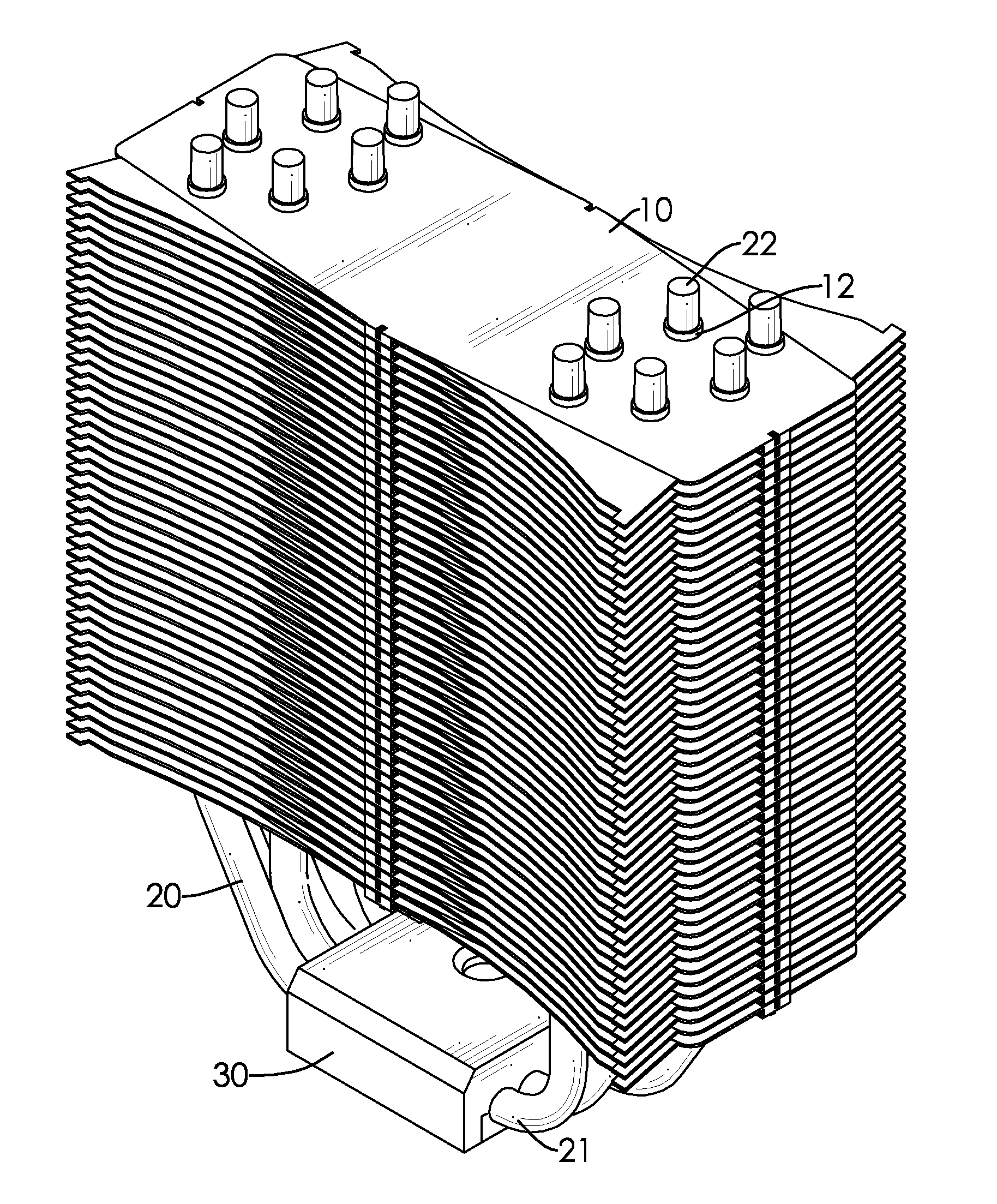
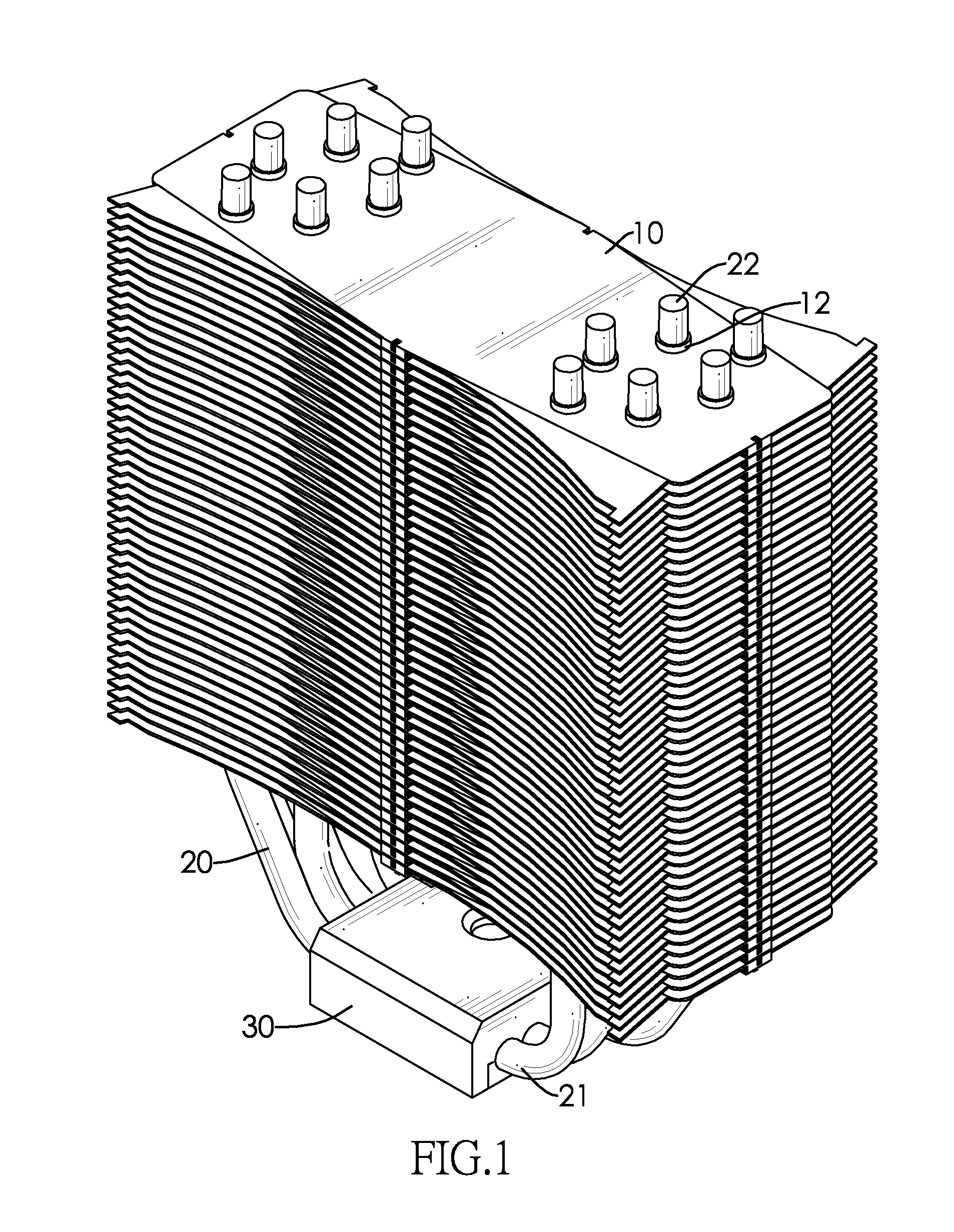
[0015]With reference to FIGS. 1 and 2, a heat sink in accordance with the present invention comprises a fin set, at least one heat pipe (20) and a metal seat (30).

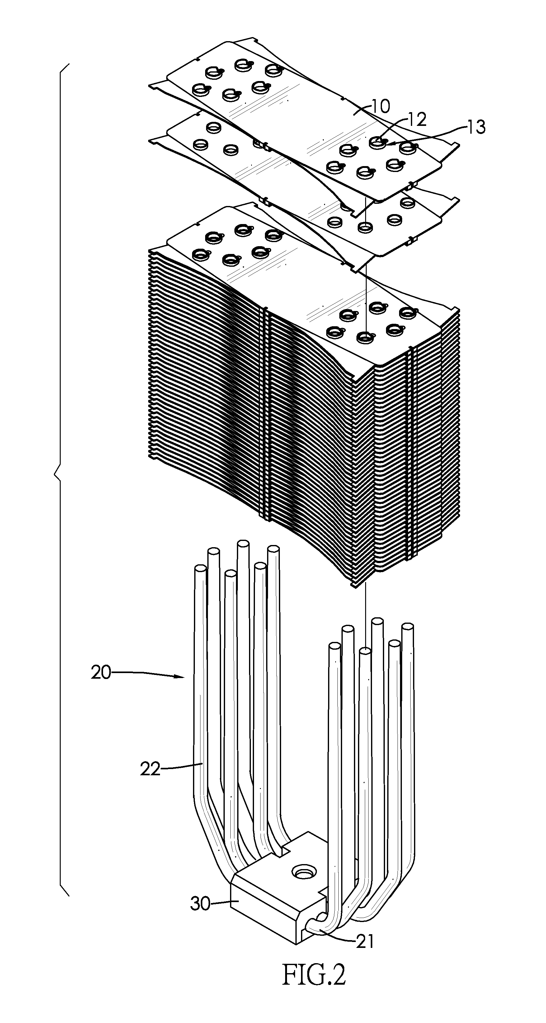
[0016]With further reference to FIG. 3, the fin set has multiple fins (10) and at least one tapered tube (11). The fins (10) are stacked in sequence and each fin (10) has at least one protrusion (12). The at least one protrusion (12) protrudes from each fin (10), has an internal surface and a tapered hole (13). The tapered hole (13) is defined through the protrusion (12) of each fin (10) and corresponds to and aligns with the tapered hole (13) of subsequent adjacent fins (10). Each tapered tube (11) is formed through the fin set and is defined in corresponding tapered holes (13) of the fins (10), each tapered tube (11) has a bottom hole edge and a top hole edge.

[0017]With further reference to FIG. 4, the at least one heat pipe (20) has at least one tapered arm corresponding to and mounted through a corresponding tapered tu...


PUM


Abstract

A heat sink has a fin set and at least one heat pipe. The fin set has multiple stacked fins and at least one tapered tube. Each fin has at least one protrusion. The at least one protrusion protrudes from each fin and each protrusion has an internal surface. The at least one tapered tube is defined through corresponding protrusions of the fins. The at least one heat pipe has at least one tapered arm and a pipe wall. The tapered arm corresponds to and is mounted through a corresponding tapered tube of the fin set. The pipe wall of the heat pipe abuts the internal surfaces of corresponding protrusions of the fins tightly so heat can be dissipated efficiently during use.

Description

BACKGROUND OF THE INVENTION[0001]1. Field of the Invention[0002]The present invention relates to a heat sink, and more particularly to a heat sink that has at least one tapered heat pipe mounted through and contacting fins tightly to improve thermal conductivity.[0003]2. Description of the Prior Arts[0004]A heat sink is connected to a central processing unit (CPU) to dissipate heat from the CPU so preventing the CPU from overheating and maintaining working efficiency.[0005]A conventional heat sink is a metal device with multiple fins and at least one heat pipe. The fins are stacked and each fin has a surface area, multiple through holes and multiple protrusions. The through holes are defined through the fins and correspond to and align with the through holes of adjacent fins. The protrusions are formed around the through holes and have inner surfaces. The at least one heat pipe abuts an electronic device and is mounted through corresponding through holes and has a pipe wall. Solder ...

Claims


Application Information

Patent Timeline
Patent Type & Authority Applications(United States)
IPC IPC(8): F28D15/04F28F7/00F28F3/02
CPCF28F3/02F28D15/04F28F7/00F28D15/0275F28F1/32
Inventor LEE, CHRIS
Owner LEA MIN TECH
Why Eureka
Try Eureka