Cooling system for cooling of at least one circulating fluid, and a machine comprising the cooling system

a cooling system and circulating fluid technology, applied in the direction of engine cooling apparatus, stationary conduit assembly, lighting and heating apparatus, etc., can solve the problems of deteriorating system efficiency and increasing the risk of breakdowns, and achieve satisfactory air flow through the unit, facilitate service and cleaning, and improve the effect of cooling system efficiency

Inactive Publication Date: 2011-09-08
ATLAS COPCO ROCK DRILLS
View PDF12 Cites 4 Cited by
  • Summary
  • Abstract
  • Description
  • Claims
  • Application Information

AI Technical Summary

Benefits of technology

[0024]In an embodiment of the cooling system the fan comprises a fan wheel placed parallel to the first side surface of the cooling unit in connection to the air inlet of the cooling unit. This position results in a satisfactory air flow through the unit and in that service and cleaning are facilitated since the wheel is arranged close to one of the openings in the unit.
[0025]In an embodiment of the cooling system the fan comprises a fan wheel placed parallel to the air outlet of the cooling unit in connection to the second side surface of the cooling unit. This position also results in a satisfactory air flow through the unit and in that service and cleaning are facilitated since the wheel is arranged close to the second opening of the unit.
[0026]In an embodiment of the cooling system, the cooling element is placed inside the inlet lamellae in the vicinity of the air inlet. This position of the cooling element is very advantageously since the air flow will pass the cooling element immediately after having passed the lamellae at the air inlet and will accordingly still have a low temperature, which is important to achieve a high cooling efficiency of the fluid in the cooling element.
[0027]In an embodiment of the cooling system deflection plates are arranged in the cooling unit in order to reduce the flow losses in the air flow and thereby ensuring the maximizing of the air flow through the cooling unit. The use of deflection plates imply that the flow losses in the air flow are reduced considerably since the deflection plates are positioned at selected places in the unit to facilitate the redirection of the air flow and reduce the vortex formation in the cooling unit.
[0028]In an embodiment of the cooling system, the inlet lamellae are turnably arranged outwardly at the air inlet. This embodiment is very advantageously since much waste and particles after some use will be accumulated on the inlet lamellae and they will be easy to clean e.g. by flushing streaming water when they are turned outwardly outside of the cooling unit.
[0029]In an embodiment of the cooling system, the cooling unit comprises rotation actuators so that when the inlet lamellae are turned outwardly, the cooling element could also be turned outside of the first side surface of the cooling unit where the air inlet is situated. Since much waste and particles after some use will be accumulated on the cooling element, which reduces its cooling efficiency of the fluid flowing through the cooling element, it is advantageously if also the cooling element easily could be cleaned, e.g. by flushing of streaming water when they are turned outwardly outside of the cooling unit.

Problems solved by technology

However, the use of the surrounding air for cooling of the fluid of the cooling system leads to some severe consequences when air pollutants and particles are accompanying the air that is flowing into the system, and / or the machine or the vehicle where they are deposited on the cooling element etc.
These deposited particles are polluting the interior of the system and / or the machine, which considerably deteriorate the efficiency of the system, and increases the risk of breakdowns considerably.

Method used


Image

  • Cooling system for cooling of at least one circulating fluid, and a machine comprising the cooling system
  • Cooling system for cooling of at least one circulating fluid, and a machine comprising the cooling system
  • Cooling system for cooling of at least one circulating fluid, and a machine comprising the cooling system

Examples


Embodiment Construction

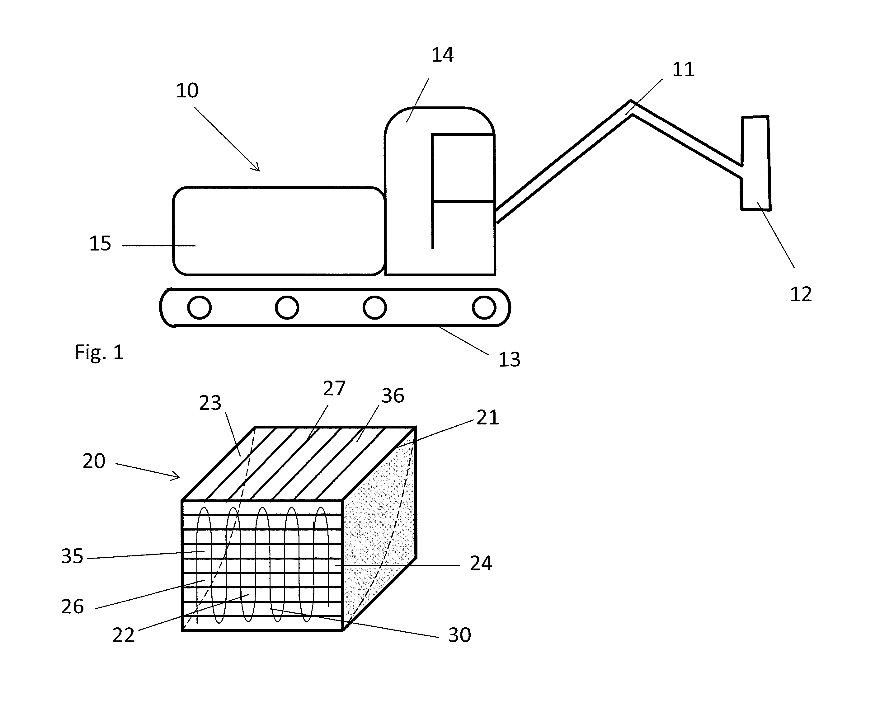
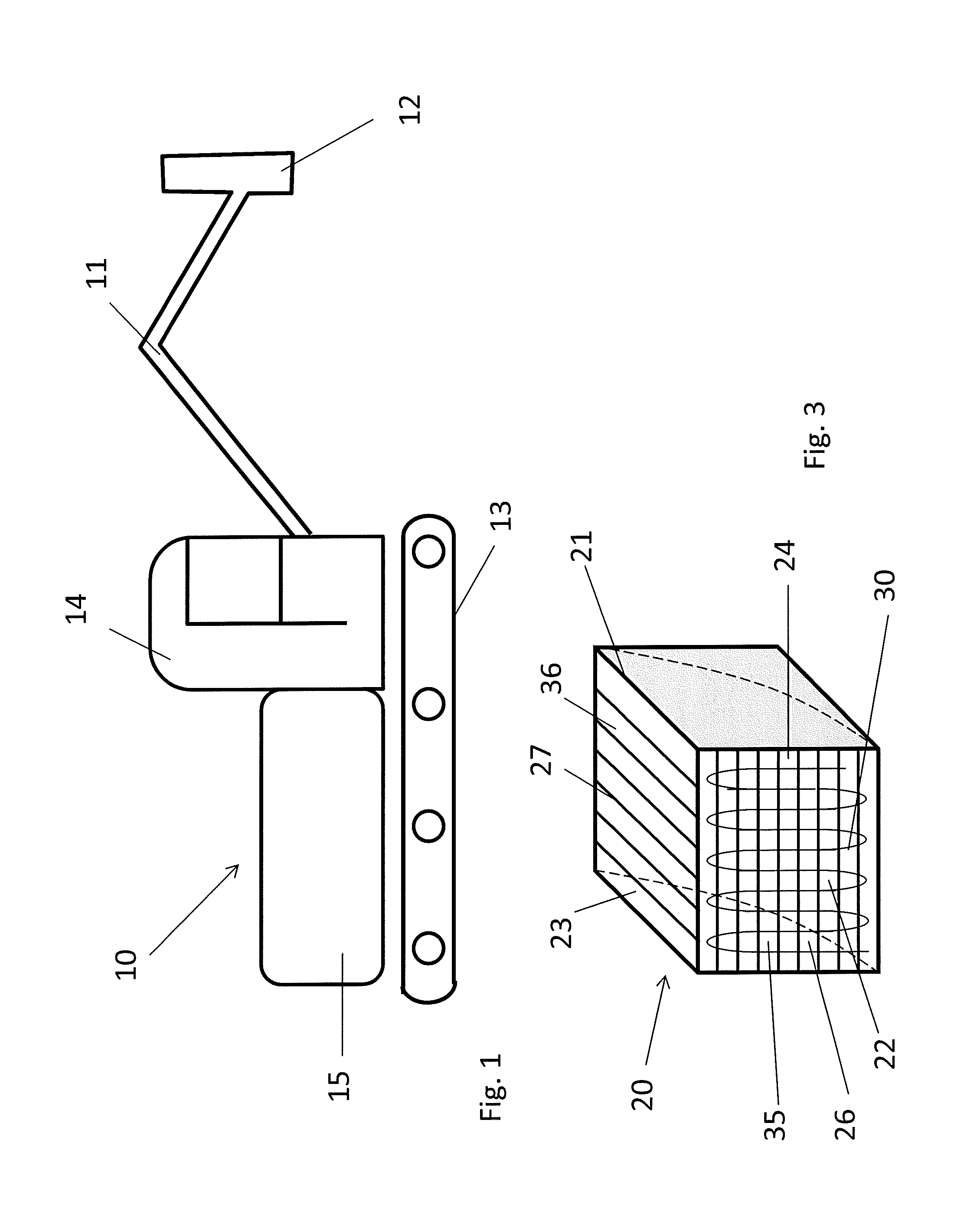
[0042]In FIG. 1, a drill rig 10 for different types of ground and construction works and in which the present invention e.g. may be used is schematically illustrated.

[0043]The drill rig comprises i.e. a longitudinal, movable arm 11, at which end drilling devices 12 are arranged, caterpillar treads 13 to propel the rig, a compartment 14 for the operator and an engine housing 15.

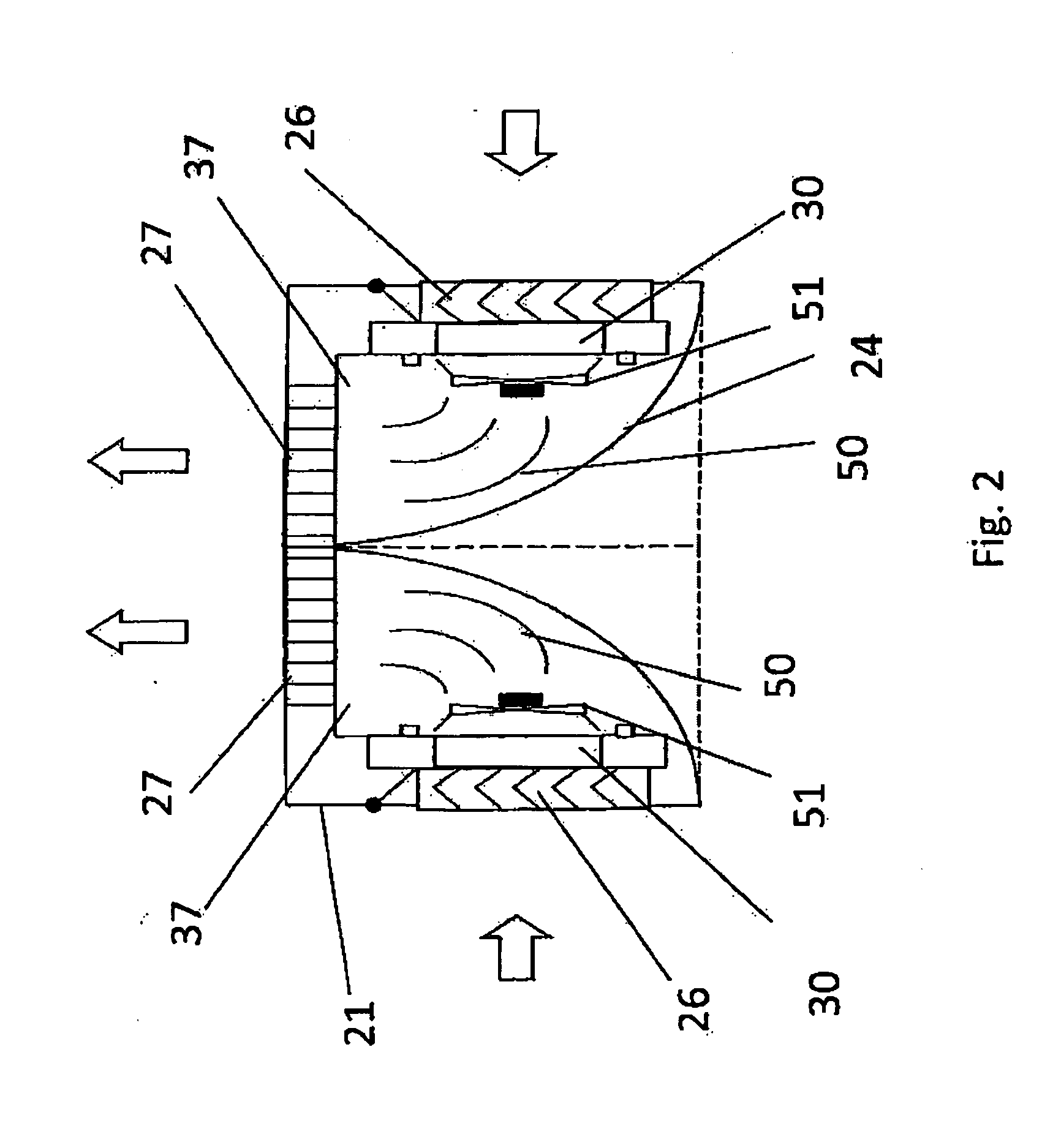
[0044]The engine housing 15 of the drill rig contains a plurality of components and systems that ensures that the rig work properly such as e.g. an engine that supplies the required power to the drill rig. Thus, the engine is used to e.g. propel the rig, move the longitudinal arm and to operate the drilling device. The engine, and a plurality of the different systems and components in the drill rig, produce a considerably amount of heat and thus, require cooling in order to avoid breakdowns and to ensure continuous operation during long periods. The necessity of cooling increases when the load is high and if t...


PUM


Abstract

The present invention concerns a cooling system for cooling of at least one circulating fluid. The cooling system comprises at least one cooling unit (20) comprising: an air inlet (22) arranged in a first side surface (35); an air outlet (23) arranged in a second side surface (36); a fan for creating an air flow through the unit from the air inlet (22) to the air outlet (23); a cooling element (30) through which at least one fluid is circulating and which is placed in the air flow through the unit (20). The invention is characterized in that the cooling unit comprises a passage (37), which extends between the air inlet (22) and the air outlet (23) through which the air flow flows and in which the flow direction of the air flow is redirected by a redirection plate (24) so that the air flow in to, and out of the cooling unit (20) are separated, and that the size of the cross section area in the air inlet (22) and along the passage (37) that extends between the air inlet (22) and the air outlet (23) as well as in the air outlet (23) is mainly constant. The invention also concerns a machine (10) comprising the cooling system according to the invention.

Description

TECHNICAL FIELD[0001]The invention relates to a cooling system for cooling of at least one circulating fluid, according to the preamble of patent claim 1.[0002]The invention furthermore relates to a machine comprising one, or a plurality, of such cooling systems according to claim 12.BACKGROUND[0003]At different types of ground and construction works, and during mining, different types of machines and vehicles are used in order to facilitate and increase the efficiency of the work. Vehicles that may be used are e.g. drill rigs, asphalting machines, excavation machines etc. In common for all these machines are that they are exposed to surrounding air comprising particles and waste material which deteriorate several of the systems and components of the machines and vehicles that are essential in order to make the machines and the vehicles work satisfactory.[0004]An important system in all these machines and vehicles is the cooling system that prevents overheating of the driving motor ...

Claims


Application Information

Patent Timeline
Patent Type & Authority Applications(United States)
IPC IPC(8): F28D15/00
CPCF01P5/06F01P11/10F04D29/582F04D29/547F04D29/541F01P11/12F28D1/0452
Inventor JACOBSSON, HENRIKTOUMAS, GORAN
Owner ATLAS COPCO ROCK DRILLS
Why Eureka
Try Eureka