Switched capacitor amplifier

Active Publication Date: 2011-09-08
ABLIC INC
View PDF7 Cites 5 Cited by
  • Summary
  • Abstract
  • Description
  • Claims
  • Application Information

AI Technical Summary

Benefits of technology

[0014]According to the present invention, the switched capacitor amplifier is capable of operating so as to eliminate a charge/discharge time difference between the input capacitor and the output capacitor. Accordingly, in the shift from a hold state to a sample state, for example, even if one terminal voltage of the output capacitor abruptly increases to the output vol

Problems solved by technology

Therefore, the output v

Method used


Image

  • Switched capacitor amplifier
  • Switched capacitor amplifier
  • Switched capacitor amplifier

Examples


Embodiment Construction

[0020]Now, referring to the accompanying drawings, an embodiment of the present invention is described below.

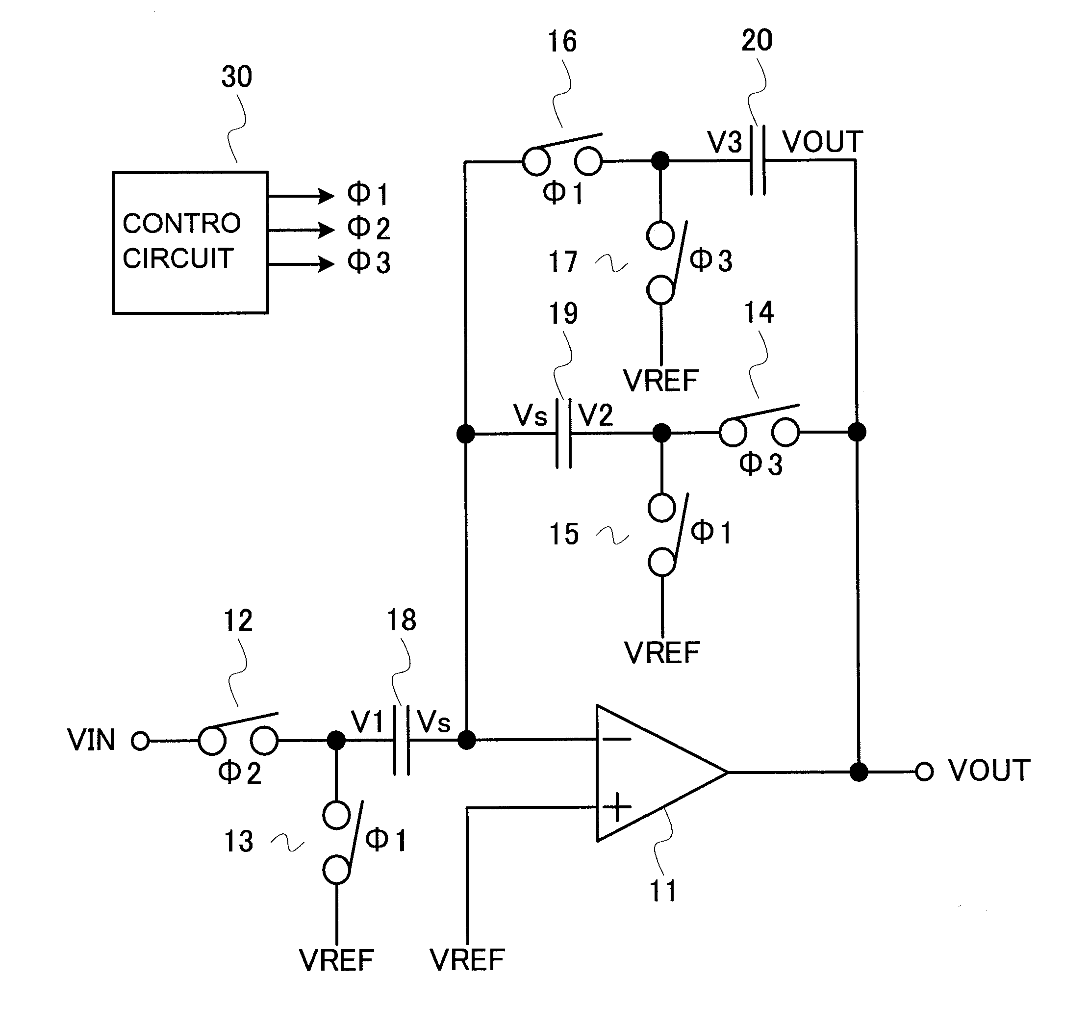
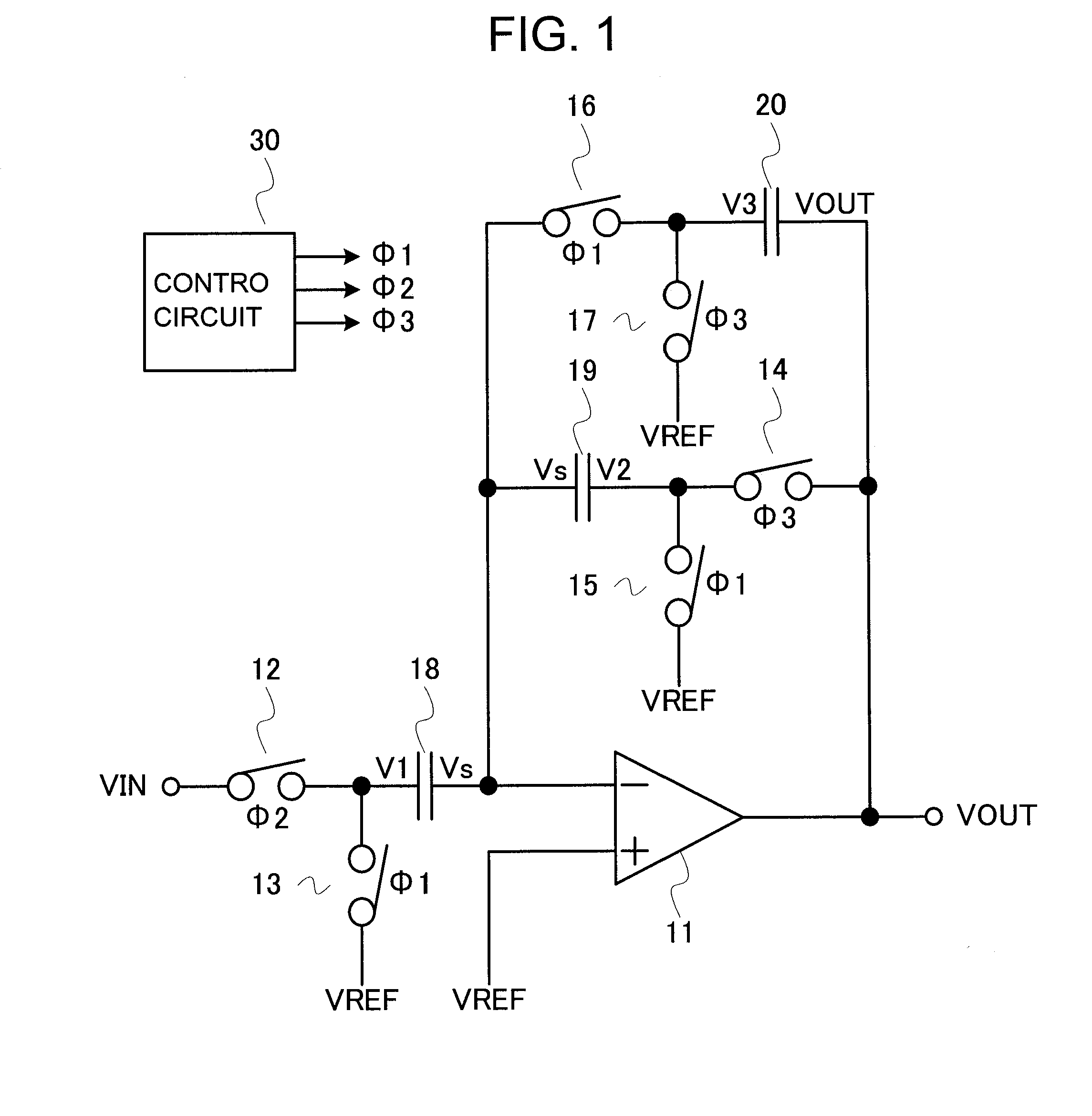
[0021]First, a configuration of a switched capacitor amplifier is described. FIG. 1 is a circuit diagram illustrating the switched capacitor amplifier.

[0022]The switched capacitor amplifier includes an internal amplifier 11, an input switch 12, a switch 13, an output switch 14, switches 15 to 17, an input capacitor 18, an output capacitor 19, a storage capacitor 20, and a control circuit 30.

[0023]The input switch 12 and the input capacitor 18 are provided in this order between an input terminal of the switched capacitor amplifier and an inverting input terminal of the internal amplifier 11. The switch 13 is provided between a connection point between the input switch 12 and the input capacitor 18, and a reference voltage input terminal of the switched capacitor amplifier. The switch 16 and the storage capacitor 20 are provided in this order between the inverting input termina...


PUM


Abstract

Provided is a switched capacitor amplifier capable of outputting a stable output voltage. The switched capacitor amplifier is capable of operating so as to eliminate a charge/discharge time difference between an input capacitor (18) and an output capacitor (19). Accordingly, in a shift from a hold state to a sample state, for example, even if one terminal voltage (V2) of the output capacitor (19) abruptly increases to an output voltage (VOUT), another terminal voltage (Vs) of the output capacitor (19) does not increase abruptly. In other words, an input voltage to an internal amplifier (11) does not increase abruptly. Therefore, an output voltage of the internal amplifier (11) becomes stable and accordingly the output voltage (VOUT) becomes stable as well.

Description

RELATED APPLICATIONS[0001]This application claims priority under 35 U.S.C. §119 to Japanese Patent Application No. 2010-049873 filed on Mar. 5, 2010, the entire content of which is hereby incorporated by reference.BACKGROUND OF THE INVENTION[0002]1. Field of the Invention[0003]The present invention relates to a switched capacitor amplifier.[0004]2. Description of the Related Art[0005]A conventional switched capacitor amplifier is described. FIG. 3 is a circuit diagram illustrating the conventional switched capacitor amplifier. FIG. 4 is a time chart illustrating an operation of the conventional switched capacitor amplifier.[0006]During sampling, a control circuit 60 controls a clock signal Φ1 to L. Accordingly, a switch 43 and switches 45 and 46 are turned OFF. The control circuit 60 controls a clock signal Φ2 to H. Accordingly, a switch 42, a switch 44, and a switch 47 are turned ON. Then, an input voltage VIN is input, and the input voltage VIN is sampled on a capacitor 48. The sa...

Claims


Application Information

Patent Timeline
IPC IPC(8): H03F11/00
CPCH03F11/00H03F2203/45514H03F3/005H03F2203/45551H03F3/45475H03F3/45H03F3/70
Inventor UCHIDA, TOSHIYUKI
Owner ABLIC INC
Why Eureka
Try Eureka