Position detection apparatus
a technology of position detection and pointing performance, which is applied in the direction of instruments, computing, electric digital data processing, etc., can solve the problems of deterioration of the position detection performance of the capacitive type system, and achieve the effects of preventing deterioration of the detection performance, increasing spatial distance, and stabilizing the position pointing performan
- Summary
- Abstract
- Description
- Claims
- Application Information
AI Technical Summary
Benefits of technology
Problems solved by technology
Method used
Image
Examples
first embodiment
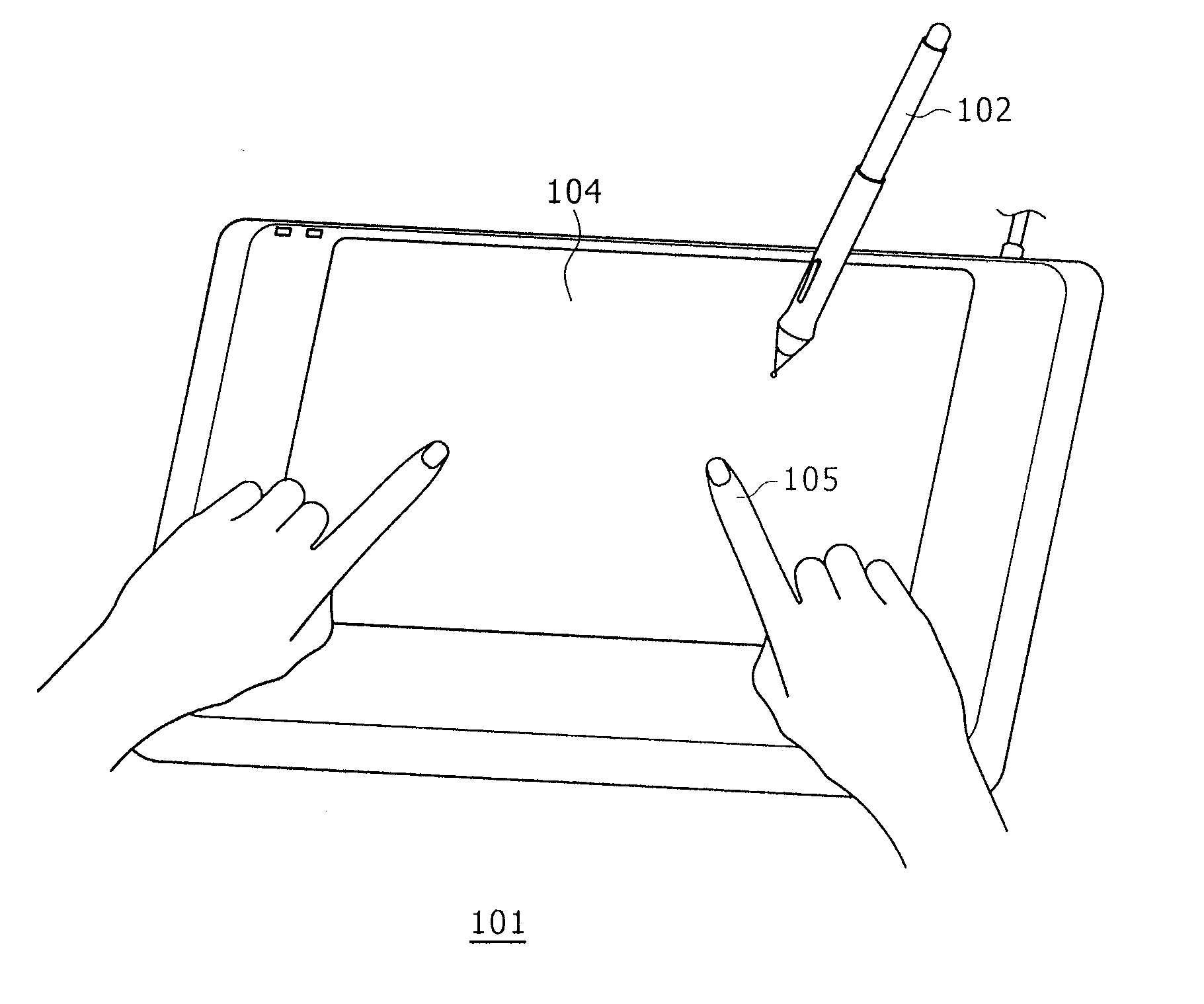
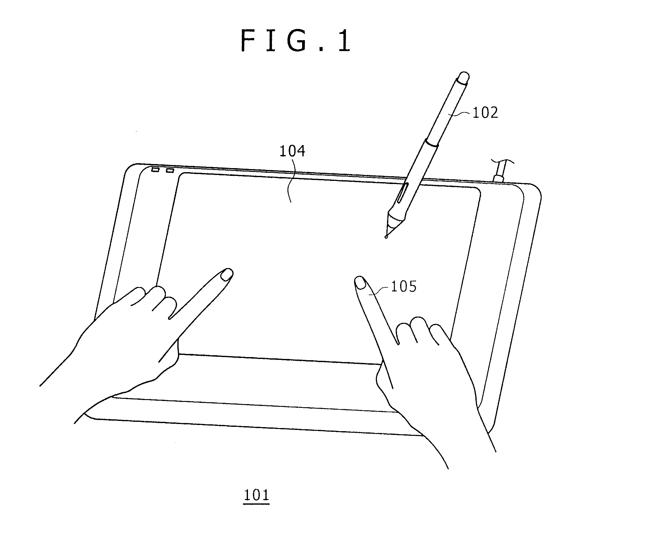
[0020]FIG. 1 is a perspective view of an entire position detection apparatus showing an example of a first embodiment of the present invention. The position detection apparatus 101 includes a position detection region 104 for detecting the positions pointed to by a pen 102 as a first position pointer and a finger 105 as a second position pointer, and position information corresponding to an operation of the pen 102 and the finger 105 is supplied to an apparatus such as a personal computer (not shown). Further, a transparent protective cover of a glass plate, an acrylic resin plate or the like, hereinafter described, is disposed on the position detection region 104, and a display section such as a known LCD display unit is disposed below the protective cover. The LCD display unit displays a signal supplied thereto from the apparatus such as a personal computer.
[0021]Accordingly, by operating the pen 102 on the position detection region 104, a user can draw on the LCD display unit. Si...
second embodiment
Frequency Interleave
[0048]FIG. 7A illustrates a signal supplied to the loop coils 408 provided in the electromagnetic type position detection section 209 (referred to as “EMR (Electro-Magnetic Resonance) driving signal”) and FIG. 7B illustrates a signal supplied to the transmission conductors 504 provided in the capacitive type position detection section 206 (referred to as capacitive driving signal).
[0049]In FIG. 7A, the oscillation circuit 402 shown in FIG. 4 generates a sine wave AC signal of a frequency (e.g., 500 KHz) substantially equal to the resonance frequency of the resonance circuit of the pen 102. In the present embodiment, the loop coils 408 include four loop coils 408a, 408b, 408c and 408d for the convenience of description, and each of the coils is placed into a selected state for a period of 64 μS by the coil selection circuit 407, which is controlled by a predetermined sequence in accordance with an instruction from the first control section 409. Further, the select...
PUM
 Abstract
Description
Claims
Application Information
 - R&D
- Intellectual Property
- Life Sciences
- Materials
- Tech Scout
- Unparalleled Data Quality
- Higher Quality Content
- 60% Fewer Hallucinations
Browse by: Latest US Patents, China's latest patents, Technical Efficacy Thesaurus, Application Domain, Technology Topic, Popular Technical Reports.
© 2025 PatSnap. All rights reserved.Legal|Privacy policy|Modern Slavery Act Transparency Statement|Sitemap|About US| Contact US: help@patsnap.com


