
Transmitter, receiver and extender system

Active Publication Date: 2011-09-08
ATEN INT CO
View PDF18 Cites 6 Cited by
  • Summary
  • Abstract
  • Description
  • Claims
  • Application Information

AI Technical Summary

Benefits of technology

[0008]The present invention is directed to a transmitter, a receiver and a signal extender system, wherein a simple architecture (e.g., one that uses the mode property of the filter and the common mode signal) is utilized and the transition minimized differential signals (TMDS) or the low voltage differential signals (LVDS) are transmitted via a single network cable (e.g., CAT5 / 5e / 6 / 7 / 7a or any other transmission medium with four twisted pairs) so that the cost is lowered and the layout is simplified.

Problems solved by technology

However, if a more expensive transmission interface, such as HDMI or DVI, is adopted to transmit the digital video-audio signals, the cost cannot be lowered.
Because the two network cables have different lengths, the layout becomes difficult, and the transmitted digital video-audio signals may become skewed or have undesirable signal delay, resulting in the receiver generating error signals after demodulation.
In addition, the above-mentioned problem also occurs when a transmitting device compliant with the Displayport standard transmits the low-voltage differential signal (LVDS) and the associated low frequency or single-end / low frequency signal.

Method used


Image

  • Transmitter, receiver and extender system
  • Transmitter, receiver and extender system
  • Transmitter, receiver and extender system

Examples


Embodiment Construction

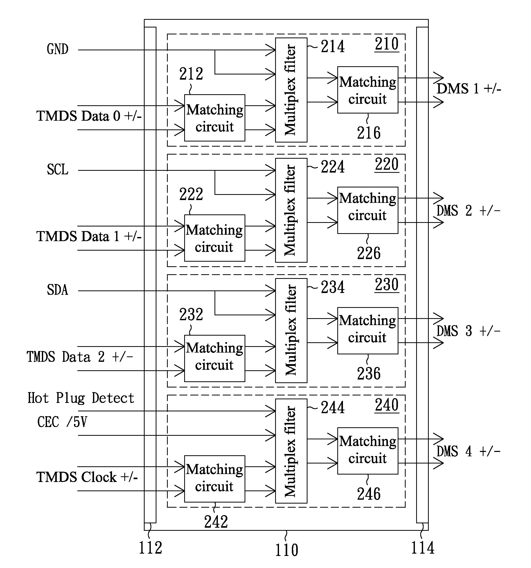
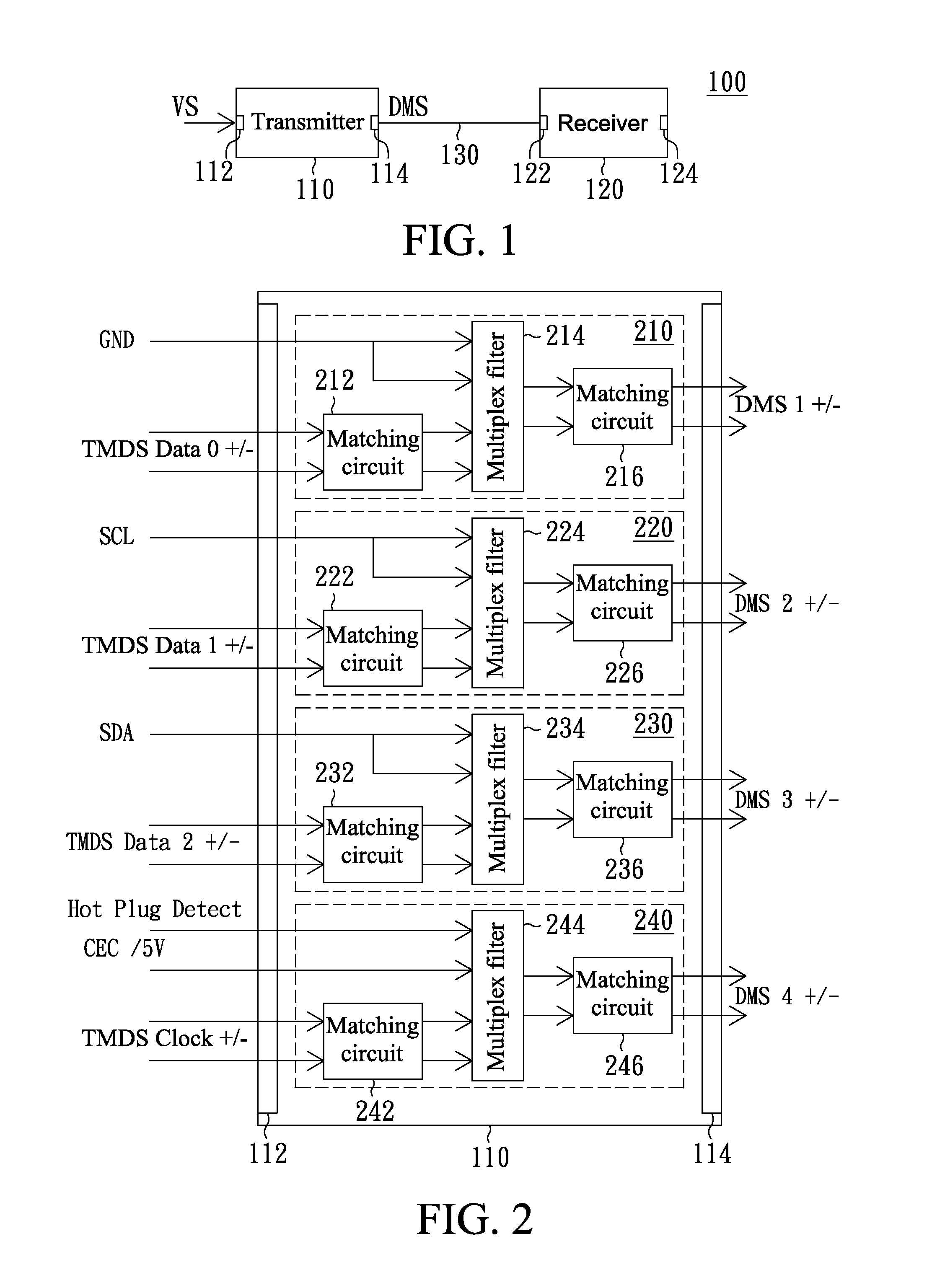
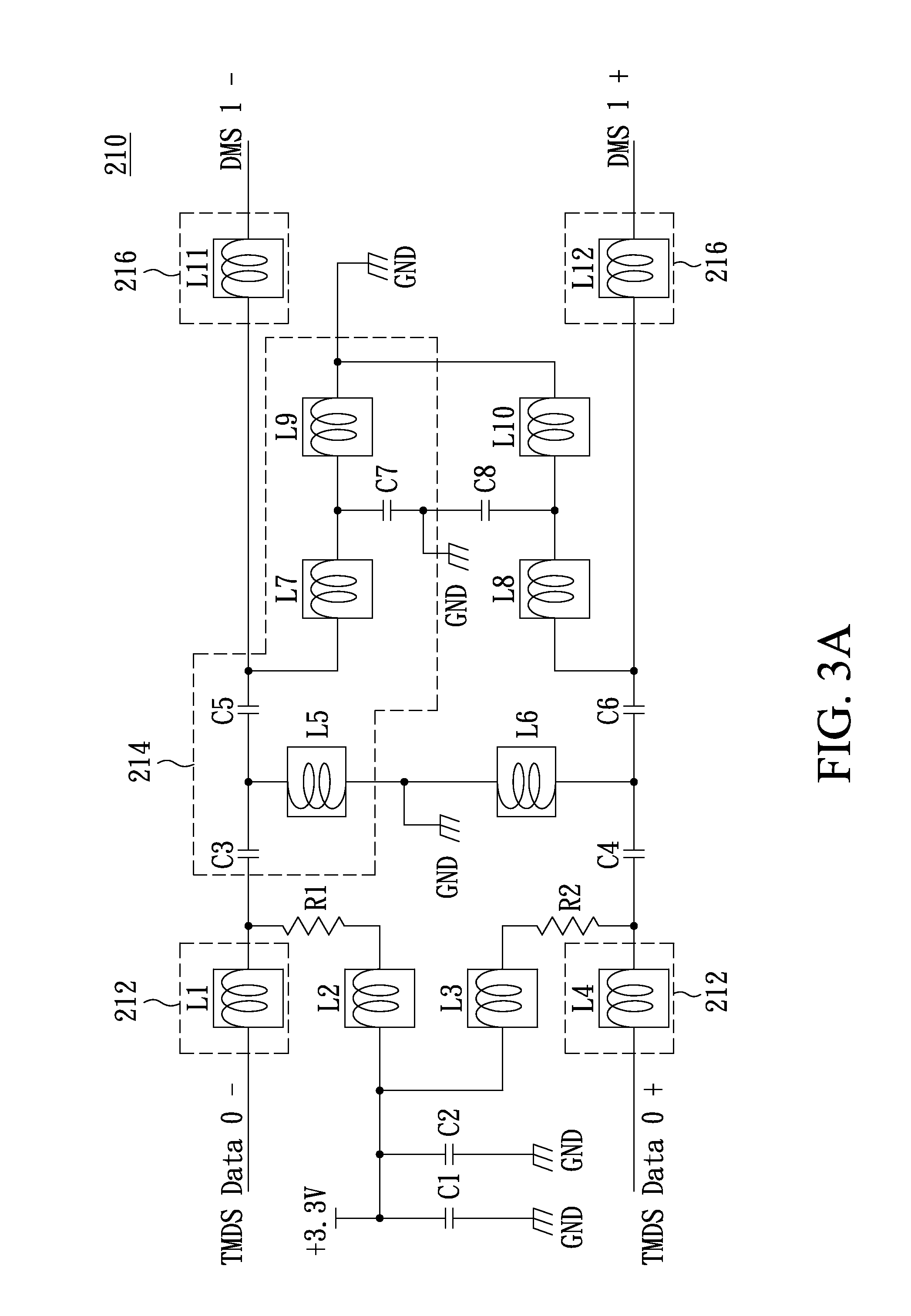
[0018]The invention provides a transmitter, a receiver and a signal extender system, wherein a simple architecture (e.g., one that uses the mode property of the filter and the common mode signal) is utilized and the digital video-audio signals are transmitted via a single network cable (e.g., CAT5 / 5e / 6 / 7 / 7a or any other transmission medium with four twisted pairs) so that the cost is lowered and the layout is simplified. The digital video-audio signal may be a high definition multimedia interface (HDMI) signal, a digital visual interface (DVI) signal or a Displayport signal. The HDMI signal and DVI signal each comprise four transition minimized differential signaling (TMDS) signals, such as the digital differential signals TMDS Data 0 + / −, TMDS Data 1 + / −, TMDS Data 2 + / − or TMDS Clock + / −. The Displayport signal includes four low voltage differential signaling (LVDS) signals, such as digital differential signals LVDS Main Link Lane 0 p / n, LVDS Main Link Lane 1 p / n, LVDS Main Link L...


PUM


Abstract

A transmitter includes a signal input terminal, multiple loading units and a communication port. The signal input terminal receives a digital video-audio signal, which comprises multiple digital differential signals and multiple single-end / low frequency signals. The loading units respectively load the corresponding single-end / low frequency signals to the digital differential signals to obtain multiple differential mixed signals. A frequency of the digital differential signals is higher than a frequency of the corresponding single-end / low frequency signals. The communication port outputs the differential mixed signals to a receiver via a network cable.

Description

BACKGROUND OF THE INVENTION[0001]1. Field of the Invention[0002]The invention relates in general to a transmitter, a receiver and a signal extender system, and more particularly to a transmitter, a receiver and a signal extender system having a simple architecture and low cost.[0003]2. Description of the Related Art[0004]Transition minimized differential signaling (TMDS) is a transmission technology developed by Silicon Image, Inc. in the United States and is adapted to an image transmission interface, such as a high definition multimedia interface (HDMI) or a digital visual interface (DVI), to ensure stability of high speed serial data transmission.[0005]Table 1 shows the transmission specifications (pin definition) of the transmission of digital video-audio signals according to the TMDS transmission technology.TABLE 1PinPin definitionPinPin definition1TMDS Data 2+2TMDS Data 2 Shield3TMDS Data 2−4TMDS Data 1+5TMDS Data 1 Shield6TMDS Data 1−7TMDS Data 0+8TMDS Data 0 Shield9TMDS Data...

Claims


Application Information

Patent Timeline
IPC IPC(8): H04N5/14
CPCH04N5/14G09G5/006G09G2370/12
Inventor SHEN, FU CHINCHIEN, KUO-CHAN
Owner ATEN INT CO
Features
  • Generate Ideas
  • Intellectual Property
  • Life Sciences
  • Materials
  • Tech Scout
  • Unparalleled Data Quality
  • Higher Quality Content
  • 60% Fewer Hallucinations
Learn More