Apparatus for detecting lane-marking on road

a technology for detecting lane markings and detection apparatuses, which is applied in the direction of traffic control systems, instruments, image enhancement, etc., can solve the problems of affecting vehicle-control functions, lane markings may not be recognized by the detection apparatus properly, and the effect of reducing detection accuracy

Active Publication Date: 2011-09-08
DENSO CORP
View PDF10 Cites 24 Cited by
  • Summary
  • Abstract
  • Description
  • Claims
  • Application Information

AI Technical Summary

Benefits of technology

[0022]Thus, since the edge points in the combined frame are set properly, even when the running direction of the vehicle and the lane-marking cross each other, the detection apparatus configured as described above can detect the lane-marking with high accuracy.

Problems solved by technology

When the painted length of the lane marking is short so that the intervals between the lane marking are long, or raised road markers only are used to separate the lanes, it is considered that the image of the lane marking does not match a frame of the image to be processed so that the lane marking may not be recognized by the detection apparatus properly.
Specifically, when the detection accuracy is decreased and if the vehicle is departing from the lane, necessary alert (e.g. departure alert) to the driver on vehicle may not be performed appropriately.
Further, some of vehicle-control functions may be affected by the decreased detection accuracy.
However, the detection apparatus is designed to combine the frames only when the linear-shape edge line cannot be generated from edges of an acquired single frame.
However, when the running direction of the vehicle is crossing the lane-marking so that the relationship of the position between the lane-marking and the road-surface image varies, if the frames are combined without any modification, the edge points of the added frame cannot be set properly.

Method used


Image

  • Apparatus for detecting lane-marking on road
  • Apparatus for detecting lane-marking on road
  • Apparatus for detecting lane-marking on road

Examples


embodiment

(1) Configuration of the Lane-Departure Warning System 1

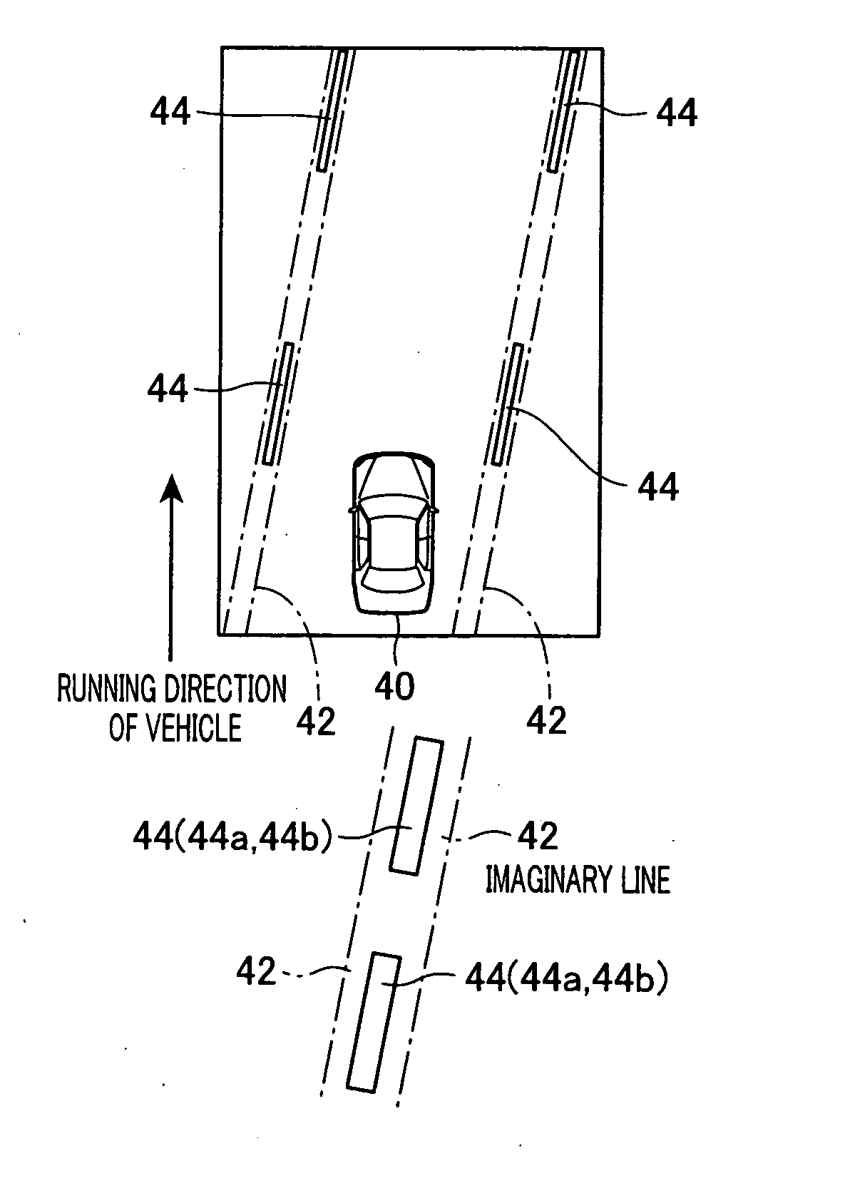
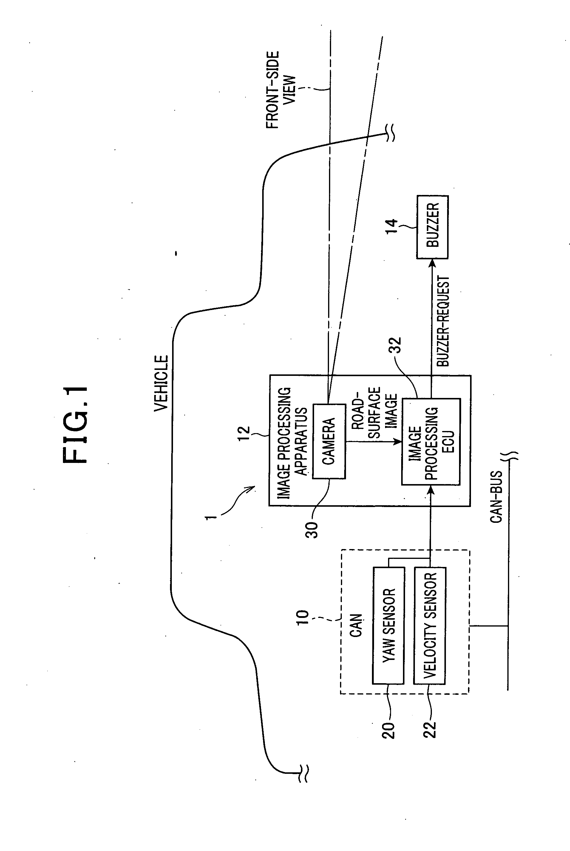
[0031]The lane-departure warning system 1 is mounted on a vehicle such as passenger cars or the like. As shown in FIG. 1, the lane-departure warning system 1 includes a vehicle network device 10 connected to CAN (control area network) bus, an image processing apparatus 12 and a buzzer 14.

[0032]The vehicle network device 10 includes a yaw rate sensor 20 for detecting an angular rate at a turning-direction of the vehicle (i.e., yaw rate) and a velocity sensor 22 that detects running speed of the vehicle. The image processing apparatus 12 includes a camera 30 and an image processing ECU (Electronic Control Unit) 32. The image processing ECU 32 is configured to process images taken by the camera 30 and outputs a buzzer-request signal to a buzzer 14. It is noted that the image processing ECU 32 serves as a detection apparatus in the present invention.

[0033]The camera 30 is mounted on the vehicle, e.g. mounted in a center portion of ...


PUM


Abstract

The image processing ECU periodically acquires road-surface images and extracts edge points in the acquired road-surface image. Subsequently, the ECU determines the operating mode and extracts the edge line when the operating mode is either a dotted mode or a frame-accumulation mode. The edge points are transformed e.g. Hough transform, to extract an edge line that most frequently passes through the edge points. The extracted edge line denotes the lane marking. The ECU outputs a signal to activate a buzzer alert when determining the vehicle may depart from the lane.

Description

CROSS REFERENCE TO RELATED APPLICATION[0001]This application is based on and claims the benefit of priority from earlier Japanese Patent Application No. 2010-046664 filed on Mar. 3, 2010, the description of which is incorporated herein by reference.TECHNICAL BACKGROUND[0002]1. Field of the Invention[0003]The present invention relates to a detection apparatus for detecting a lane marking on a road, and more particularly to an on-vehicle detection apparatus for detecting the lane marking based on road-surface images detected from an area in front of the vehicle.[0004]2. Description of the Related Art[0005]Conventionally, there have been disclosed detection apparatuses capable of detecting the lane marking on the road based on an image-processing result processed from detected road-surface images from an area in front of the vehicle. The lane marking is referred to as a line on the road which is used to differentiate traffic lanes for running vehicles. The lane marking is generally pro...

Claims


Application Information

Patent Timeline
Patent Type & Authority Applications(United States)
IPC IPC(8): G06K9/00
CPCG06K9/00G06F18/00G06V20/588G06V10/48G08G1/167G06T2207/30256
Inventor SUZUKI, SHUNSUKE
Owner DENSO CORP
Why Eureka
Try Eureka