
Method and device for optical switching

a technology of optical switching and optical switching matrix, applied in the field of communication technology, can solve the problems of significant increase in control complexity, increase in network cost, and increase in optical switching cost, and achieve the effect of reducing the demand for the switch matrix

Inactive Publication Date: 2011-09-08
HUAWEI TECH CO LTD
View PDF1 Cites 8 Cited by
  • Summary
  • Abstract
  • Description
  • Claims
  • Application Information

AI Technical Summary

Benefits of technology

The present invention provides a method and device for optical switching that saves switching ports. The optical switching device includes an optical switching unit and an optical grouping unit. The optical switching unit controls transmission paths of optical signals, while the optical grouping unit groups optical signals. The method involves receiving input optical signals, switching them to the optical grouping unit for grouping, and then switching them to output ports for outputting. The technical effect of this invention is that it reduces the demand for a switch matrix, saving ports of the optical switching unit.

Problems solved by technology

Meanwhile, the DWDM technologies make the network cost and the control complexity increased significantly.
As the number of the wavelengths accommodated in an optical fiber is up to hundreds, the number of ports for optical fiber switching and wavelength switching in optical cross-connect (OXC) is largely increased, and the cost of the optical switching is increased significantly.
At the same time, the larger the scale of the OXC is, the more difficult and complex the control of the OXC will be.
It is assumed that 20 input optical fibers and 20 output optical fibers are provided at a node, and 100 wavelengths are transmitted in each optical fiber simultaneously; if a common OXC node is used, 2000 input ports, 2000 output ports, and a 2000×2000 optical switch matrix are needed, resulting in high cost and complexity of the OXC.

Method used


Image

  • Method and device for optical switching
  • Method and device for optical switching
  • Method and device for optical switching

Examples


embodiment 1

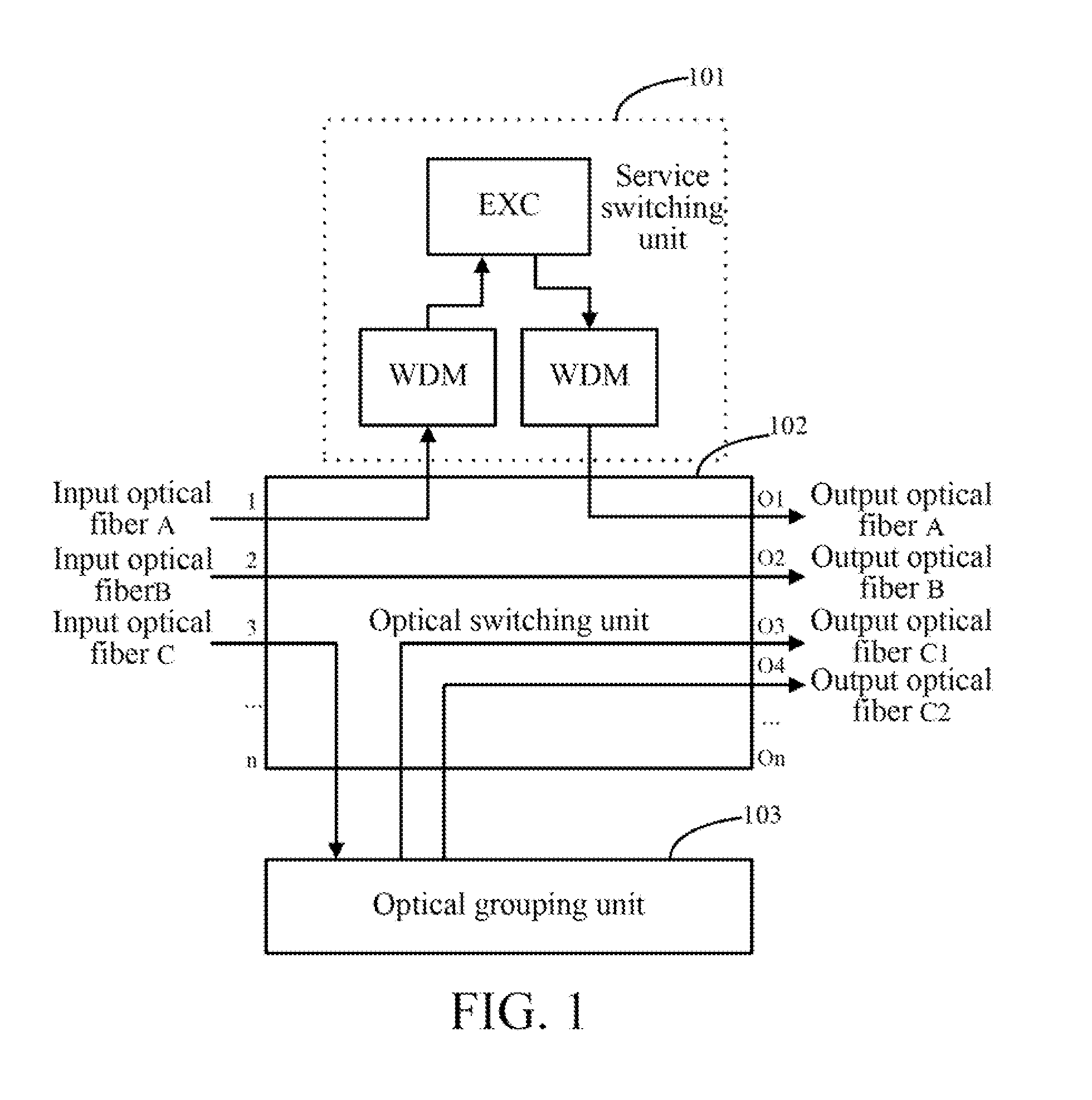
[0040]As shown in FIG. 1, an optical switching device according to this embodiment of the present invention includes an optical switching unit 102, an optical grouping unit 103, and a service switching unit 101. This embodiment of the present invention is illustrated with multi-granularity switching as the background.

[0041]The optical switching unit 102 has optical input ports and optical output ports, where a part of the optical output ports are connected to input ports of the optical grouping unit 103.

[0042]The optical grouping unit 103 has the optical input ports and optical output ports, where the optical input ports of the optical grouping unit 103 are connected to the optical output ports of the optical switching unit 102, and the optical output ports of the optical grouping unit 103 are connected to the optical input ports of the optical switching unit 102.

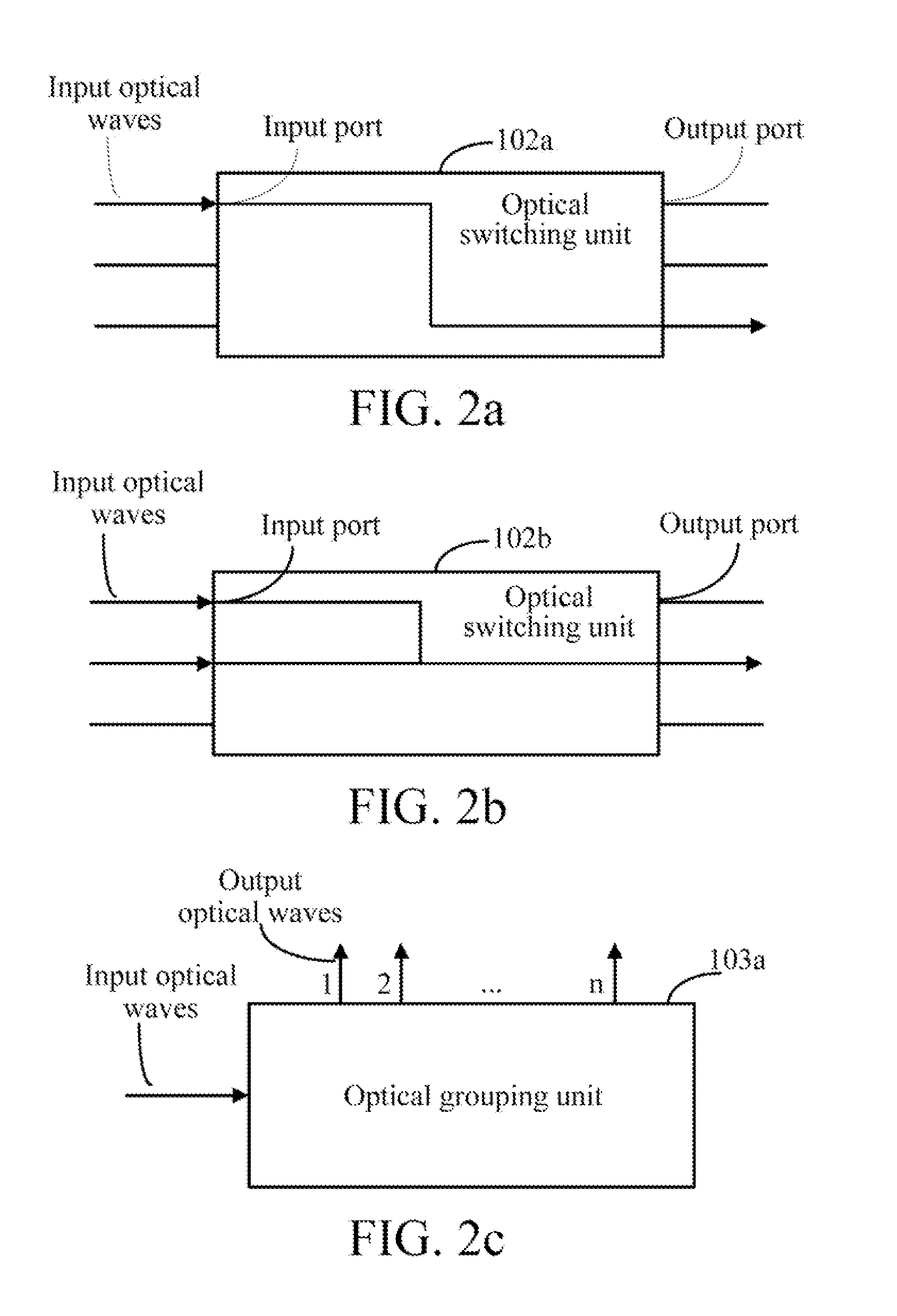
[0043]The optical switching unit 102 is configured to control transmission paths of optical signals. For example, as show...

embodiment 2

[0055]An embodiment of the present invention further provides an optical switching device. This embodiment of the present invention is illustrated with sharing of an optical grouping unit as the background.

[0056]As shown in FIG. 3a, the device may include an optical switching unit 302 and an optical grouping unit 303. The extension of the dimension is realized through sharing of an optical grouping sub-unit. It is assumed that at time T1, an optical fiber A is required to output 9 dimensions, and an optical fiber B is required to output 17 dimensions. As shown in FIG. 3b, at time T2, the optical fiber A is required to output 17 dimensions, and the optical fiber B is required to output 9 dimensions. As shown in FIG. 3c, at time T3, the optical fiber A is required to output 7 dimensions, the optical fiber B is required to output 6 dimensions, and the optical fiber A7 and the optical fiber B6 need to be combined into 1 dimension.

[0057]In this embodiment, the optical switching unit may ...

embodiment 3

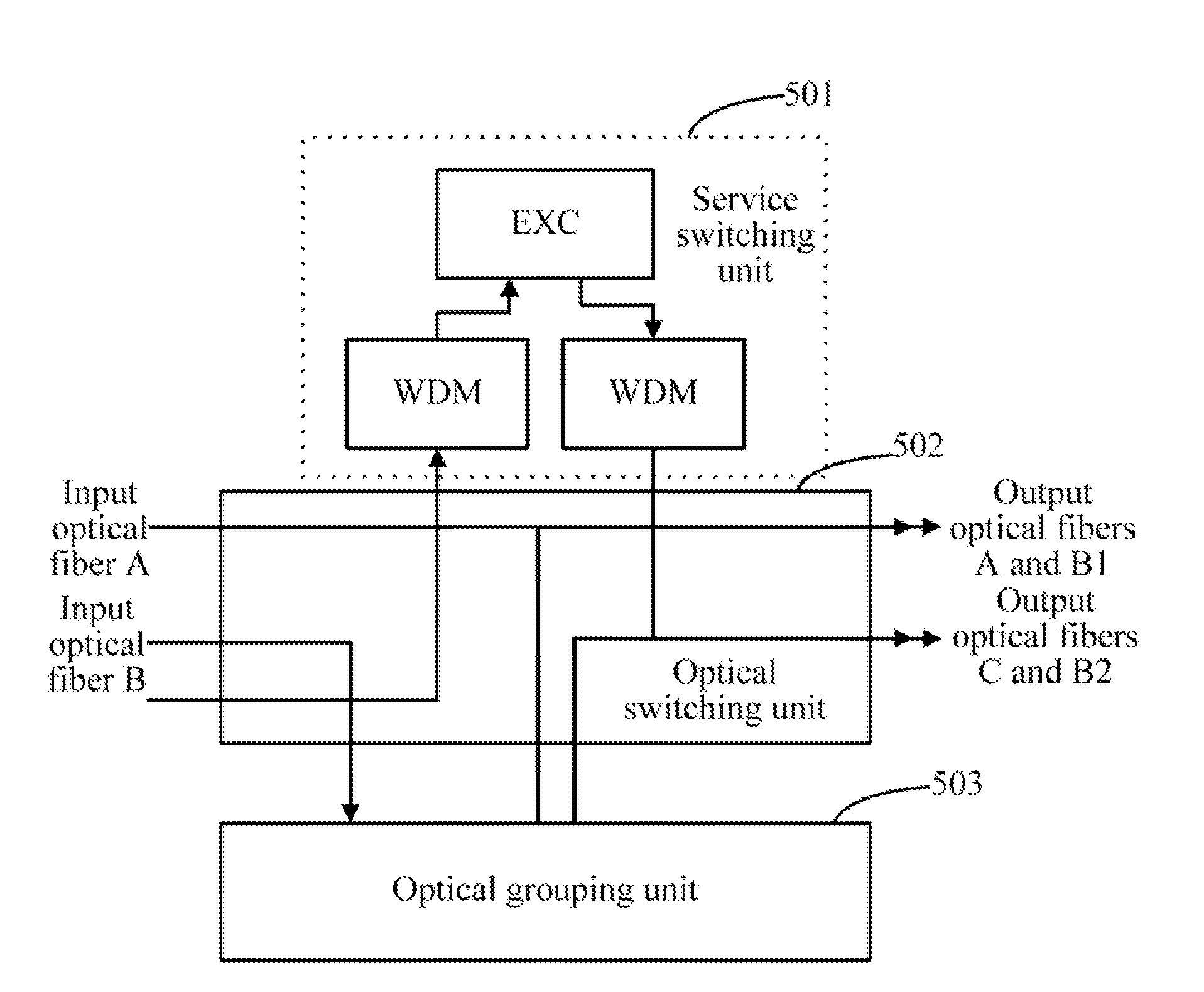
[0070]An embodiment of the present invention provides an optical switching device. This embodiment of the present invention is illustrated with dimension extension as the background.

[0071]As shown in FIG. 4a, the device includes an optical switching unit 402 and an optical grouping unit 403.

[0072]In this embodiment, wavelengths of the input optical fiber B are initially grouped into groups B1 and B2. Now, it is assumed that the wavelengths of the input optical fiber B need to be grouped into n groups, the input optical fiber B is input to the optical grouping unit 403 through the optical switching unit 402, and the optical grouping unit 403 groups the wavelengths into n groups and then sends the grouped wavelengths to the optical switching unit 402, so that the optical grouping' unit 403 can output the n groups to any output ports, realizing the output grouping and extension. The extension of the optical grouping unit 403 is implemented by extending optical grouping sub-units.

[0073]...


PUM


Abstract

A method and a device for optical switching are disclosed. The method includes: receiving input optical signals; switching the input optical signals to an optical grouping unit when the input optical signals need to be grouped, and then receiving grouped optical signals; and switching the grouped optical signals to corresponding output ports for outputting. The device includes an optical switching unit and an optical grouping unit. A part of output ports of the optical switching unit are connected to input ports of the optical grouping unit, and output ports of the optical grouping unit are connected to input ports of the optical switching unit. The optical switching unit is configured to control transmission paths of the optical signals, and the optical grouping unit is configured to group the optical signals.

Description

CROSS-REFERENCE TO RELATED APPLICATIONS[0001]This application is a continuation of International Application No. PCT / CN2009 / 074979, filed on Nov. 17, 2009, which claims priority to Chinese Patent Application No. 200810177646.1, filed on Nov. 20, 2008, both of which are hereby incorporated by reference in their entireties.[0002]FIELD OF THE TECHNOLOGY[0003]The present invention relates to the field of communications technology, and more particularly to a method and a device for optical switching.BACKGROUND OF THE INVENTION[0004]The current dense wavelength division multiplexing (DWDM) technologies enable one optical fiber to accommodate hundreds of wavelengths, and each wavelength has a transmission rate of up to 40 Gbit / s or even 100 Gbit / s, and the capacity of one optical fiber is up to the magnitude of Tbit / s, meeting demands for network bandwidth. Meanwhile, the DWDM technologies make the network cost and the control complexity increased significantly. As the number of the wavele...

Claims


Application Information

Patent Timeline
Patent Type & Authority Applications(United States)
IPC IPC(8): H04J14/02H04J14/00
CPCH04J14/0213H04J14/0217H04Q11/0005H04Q2011/0075H04Q2011/0024H04Q2011/0052H04Q2011/0016
Inventor ZHANG, GUANGYONGSHEN, SHUQIANG
Owner HUAWEI TECH CO LTD
Learn More