
Method for manufacturing an optical filter for a stereoscopic image display device

a three-dimensional image display and optical filter technology, applied in the direction of instruments, polarising elements, photo-taking processes, etc., can solve the problems of increasing the price of the product with the use of shutter glasses, the limitation of the viewing angle, and the difficulty of converting a 2d image into a 3d image, so as to simplify the manufacturing process and improve productivity and process efficiency.

Active Publication Date: 2011-09-08
LG CHEM LTD
View PDF3 Cites 30 Cited by
  • Summary
  • Abstract
  • Description
  • Claims
  • Application Information

AI Technical Summary

Benefits of technology

[0012]An aspect of the present invention provides a method for manufacturing an optical filter for a 3D image display device, which is capable of improving productivity and process efficiency by simplifying its manufacturing process.

Problems solved by technology

The two methods are advantageous in that glasses are not required; however, they are disadvantageous in that the effective viewing angle in which to obtain a 3D effect is significantly narrow, allowing only a single person to view a 3D image, and it is difficult to convert a 2D image into a 3D image.
However, the 3D display device using the shutter glasses method is disadvantageous in that the use of the shutter glasses increase the price of the product and an observer is directly exposed to electromagnetic waves generated by the driving of the shutter glasses.
The polarized glasses method is disadvantageous in that an observer must wear the polarized glasses, but is advantageous in that limitations on the viewing angle are small and the manufacturing thereof is easy.
However, the manufacturing method disclosed in U.S. Pat. No. 5,327,285 is problematic in that it entails a complicated manufacturing step due to chemical etching, has high manufacturing costs, and has low productivity.
The polarizing filter manufacturing method disclosed in Korean Patent Application No. 2000-0087186 is problematic in that it is actually somewhat difficult to control the chiral characteristics of the retarding material by using the intensity of light, resulting in low yield and instability according to temperature.

Method used


Image

  • Method for manufacturing an optical filter for a stereoscopic image display device
  • Method for manufacturing an optical filter for a stereoscopic image display device
  • Method for manufacturing an optical filter for a stereoscopic image display device

Examples


Embodiment Construction

[0020]Exemplary embodiments of the present invention will now be described in detail with reference to the accompanying drawings. The invention may, however, be embodied in many different forms and should not be construed as being limited to the embodiments set forth herein. Rather, these embodiments are provided so that this disclosure will be thorough and complete, and will fully convey the scope of the invention to those skilled in the art. In the drawings, the thicknesses of layers and regions are exaggerated for clarity. Reference numerals in the drawings denote like elements, and thus their description will be omitted.

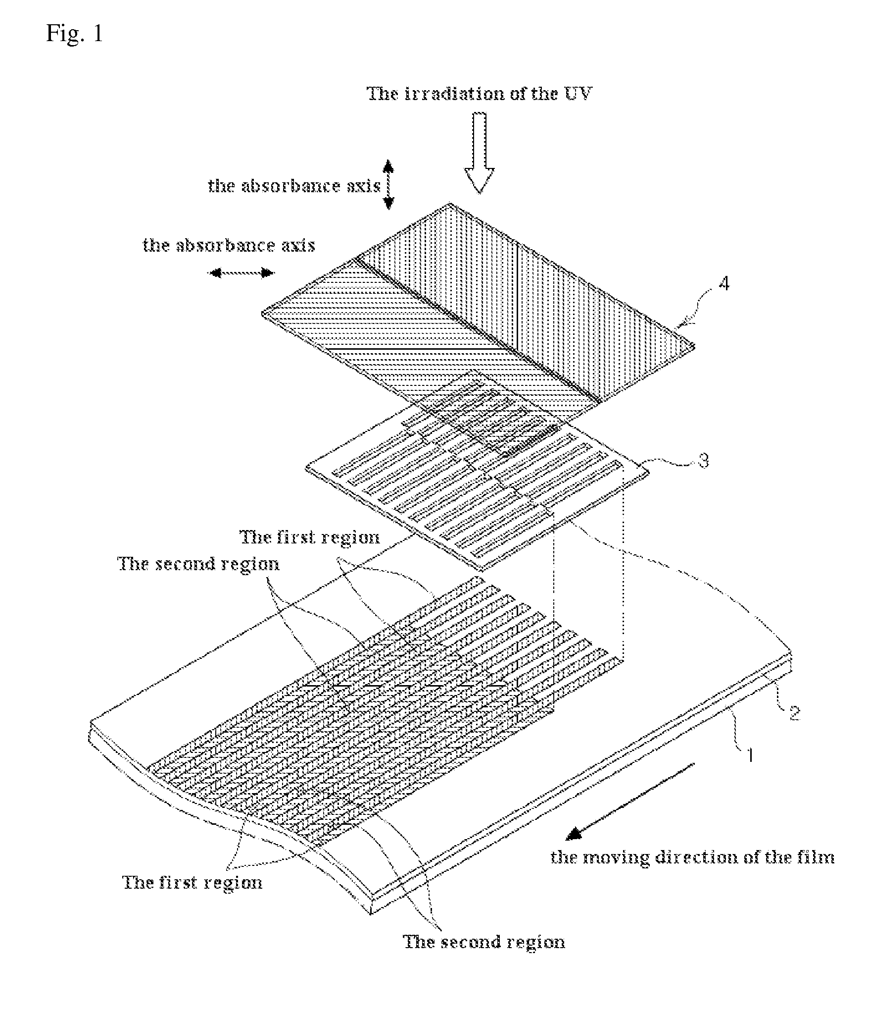
[0021]An embodiment of the present invention provides a method for manufacturing an optical filter, which is used in a 3D image display device using the polarized glasses method, having a simpler process and greater process efficiency, as compared with the conventional art. Different orientations are assigned to a fine region of a polymer layer via one-time conti...


PUM


Abstract

The present invention relates to a method for manufacturing an optical filter for a three-dimensional image display device, which forms an alignment layer having different orientating directions along a fine region via a one-time continuous optical orientation process. The method comprising: forming a polymer layer on a substrate; a photo-orienting step comprising positioning a pattern mask above the polymer layer, the pattern mask having alternating light transmission regions and light shield regions arranged in both horizontal and a vertical directions to selectively transmit different polarized light, positioning a polarizer above the pattern mask where the polarizer has two distinguishable regions that transmit different polarized light, and downwardly irradiating UV light onto the polymer layer from above the polarizer, thereby forming an alignment layer having different orientating directions in fine regions of the polymer layer; and forming a retardation layer on the orientation layer. The alignment layer in which the fine regions with different orientating directions are formed alternately and continuously is obtained via a one-time continuous photo-orientation process. Therefore, the photo-orientation process and the method for manufacturing the optical filter are simplified in comparison with the conventional art. As a result, the process yield and productivity in the manufacturing of an optical filter for a 3D image display device are improved.

Description

BACKGROUND OF THE INVENTION[0001]1. Field of the Invention[0002]The present invention relates to a method for manufacturing an optical filter for a three-dimensional image display device, and more particularly, to a method for manufacturing an optical filter for a three-dimensional image display device, which forms an alignment layer having different orientating directions along a fine region via a one-time continuous optical orientation process.[0003]2. Description of the Related Art[0004]Three-dimensional (3D) image display technology is technology that displays a 3D image as if the object actually exists in 3D space. 3D image display technology is expected to lead the next generation of display devices as a new concept in realistic image display technology improving on the level of planar visuals.[0005]A 3D effect is realized via a procedure in which the left and right images of an object, perceived by the left and right eyes, are processed by the brain. That is, since a person's...

Claims


Application Information

Patent Timeline
IPC IPC(8): G03F7/20G02B30/25
CPCG02B5/3083G02B27/2214G02F2001/133538G02F1/1303G02F1/133788G02B27/26G02B30/25G02F1/133538G02B5/30G02F1/1337G02B30/27
Inventor KIM, SIN-YOUNGPARK, MOON-SOOJEON, BYOUNG-KUNHAN, SANG-CHOLLSHIN, BU GONYOON, HYUK
Owner LG CHEM LTD
Learn More