Capacity Control System for Variable Capacity Compressor and Display Device for the System

a compressor and capacity control technology, applied in the direction of instruments, heat measurement, lighting and heating apparatus, etc., can solve the problems of inability to achieve the original purpose of applying the variable capacity compressor to the air conditioning system, engine stalls, engine speed control instabilities, etc., to achieve effective stabilization of engine control, improve accuracy, and high accuracy

Inactive Publication Date: 2011-09-15
SANDEN CORP
View PDF2 Cites 36 Cited by
  • Summary
  • Abstract
  • Description
  • Claims
  • Application Information

AI Technical Summary

Benefits of technology

[0014]A second object of the present invention is to provide a capacity control system for a variable capacity compressor, which system is capable of accurately calculating drive load of the variable capacity compressor at all times including a situation where the variable capacity compressor is operating with a maximum discharge capacity.
[0051]With the display device according to claims 21 to 25, it is possible to promote saving of the energy consumed by the variable capacity compressor while the air conditioning system is used. It is also possible to raise the environmental awareness of the user using the air conditioning system.

Problems solved by technology

As a result, instability of the engine speed control or engine stall may possibly be caused during the idling of the vehicle, for example.
In addition, if the torque of the variable capacity compressor cannot be accurately calculated, it is difficult to attain the original purpose of applying the variable capacity compressor to an air conditioning system, namely, to reduce the motive power consumed by the air conditioning system or the vehicle and thereby save energy as countermeasures against global warming.

Method used


Image

  • Capacity Control System for Variable Capacity Compressor and Display Device for the System
  • Capacity Control System for Variable Capacity Compressor and Display Device for the System
  • Capacity Control System for Variable Capacity Compressor and Display Device for the System

Examples


Embodiment Construction

[0097]Capacity control systems for a variable capacity compressor according to the present invention will be described below with reference to the drawings.

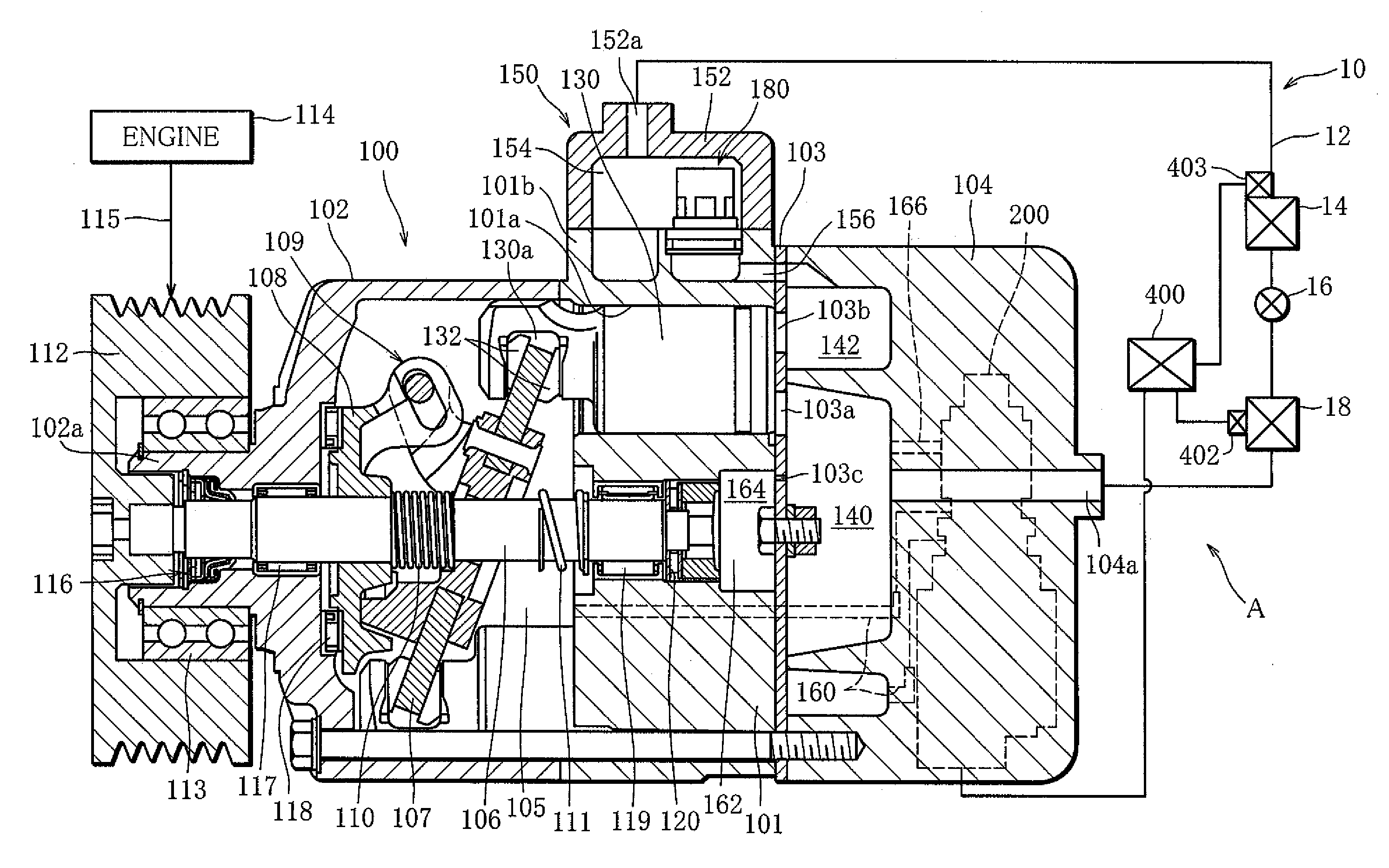
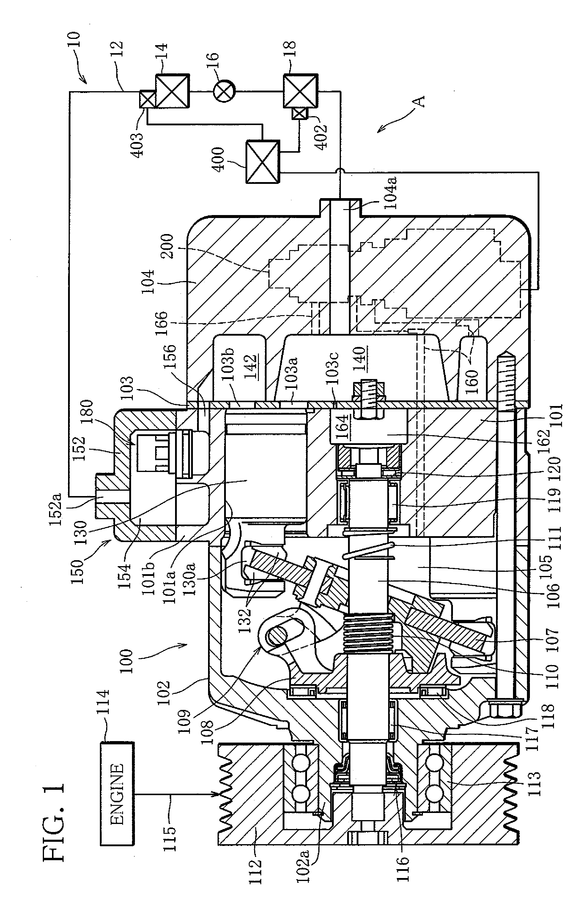
[0098]FIGS. 1 through 8 illustrate a capacity control system for a variable capacity compressor according to one embodiment of the present invention. In this embodiment, the capacity control system A of the invention is applied to a refrigeration cycle of an automotive air conditioning system.

[0099]As illustrated in FIG. 1, the refrigeration cycle 10 of the automotive air conditioning system comprises a circulation path 12 through which a refrigerant as a working fluid is circulated. A variable capacity compressor 100, a heat radiator (condenser) 14, an expansion device (thermostatic automatic expansion valve) 16 and an evaporator 18 are successively inserted in the circulation path 12 in the order mentioned as viewed in the flowing direction of the refrigerant. The variable capacity compressor 100 is operated to perform a series...


PUM


Abstract

A capacity control system for a variable capacity compressor includes target suction pressure setting means for setting, based on external information input from external information detection means, a target suction pressure for controlling the pressure in a suction pressure region as a control target, suction pressure estimation means for estimating, based on the external information, a pressure that is estimated to prevail in the suction pressure region if the variable capacity compressor is operated with a maximum discharge capacity, and discharge capacity determination means for determining, based on the suction pressure estimated by the suction pressure estimation means and the target suction pressure set by the target suction pressure setting means, whether the variable capacity compressor is operating with the maximum discharge capacity or with a controlled discharge capacity.

Description

TECHNICAL FIELD[0001]The present invention relates to a capacity control system for a variable capacity compressor used in an air conditioning system and a display device for use with the capacity control system.BACKGROUND ART[0002]A reciprocating-type variable capacity compressor used in an automotive air conditioning system, for example, includes a housing having a discharge chamber, a suction chamber, a crank chamber and cylinder bores defined therein. A drive shaft extending through the crank chamber is coupled with a swash plate such that the swash plate is tiltable relative to the drive shaft. A conversion mechanism including the swash plate converts rotation of the drive shaft to reciprocating motion of pistons received in the respective cylinder bores. The reciprocating motion of each piston causes a series of processes to take place, the processes including a suction process in which a working fluid is sucked from the suction chamber into the corresponding cylinder bore, a ...

Claims


Application Information

Patent Timeline
Patent Type & Authority Applications(United States)
IPC IPC(8): F25B49/00F25B49/02
CPCB60H1/3208F25B2700/21173B60H2001/3261B60H2001/3266B60H2001/3275F04B27/1804F04B2027/1827F04B2027/1854F04B2027/1859F04B2027/1872F25B49/022F25B2400/076F25B2500/19F25B2600/0262F25B2600/2521F25B2700/171F25B2700/173F25B2700/1931F25B2700/2104F25B2700/2106B60H2001/325
Inventor TAGUCHI, YUKIHIKO
Owner SANDEN CORP
Why Eureka
Try Eureka