Photoelectric conversion device and manufacturing method thereof

Inactive Publication Date: 2011-09-15
SAMSUNG SDI CO LTD
View PDF3 Cites 8 Cited by
  • Summary
  • Abstract
  • Description
  • Claims
  • Application Information

AI Technical Summary

Benefits of technology

[0008]It is another aspect of the present invention to provide a photoelectric conversion device having improved sealing performance at an electrolyte injection hole and a simplified sealing process, and a manufacturing method thereof.

Problems solved by technology

The wafer-type silicon or crystal solar cells have a drawback, however, in that the manufacturing costs are high due to the process characteristic of forming and handling a highly pure semiconductor material.

Method used


Image

  • Photoelectric conversion device and manufacturing method thereof
  • Photoelectric conversion device and manufacturing method thereof
  • Photoelectric conversion device and manufacturing method thereof

Examples


Embodiment Construction

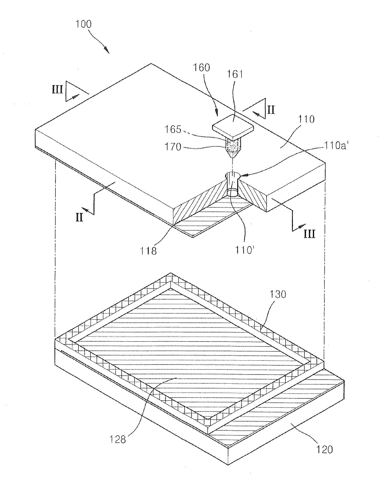
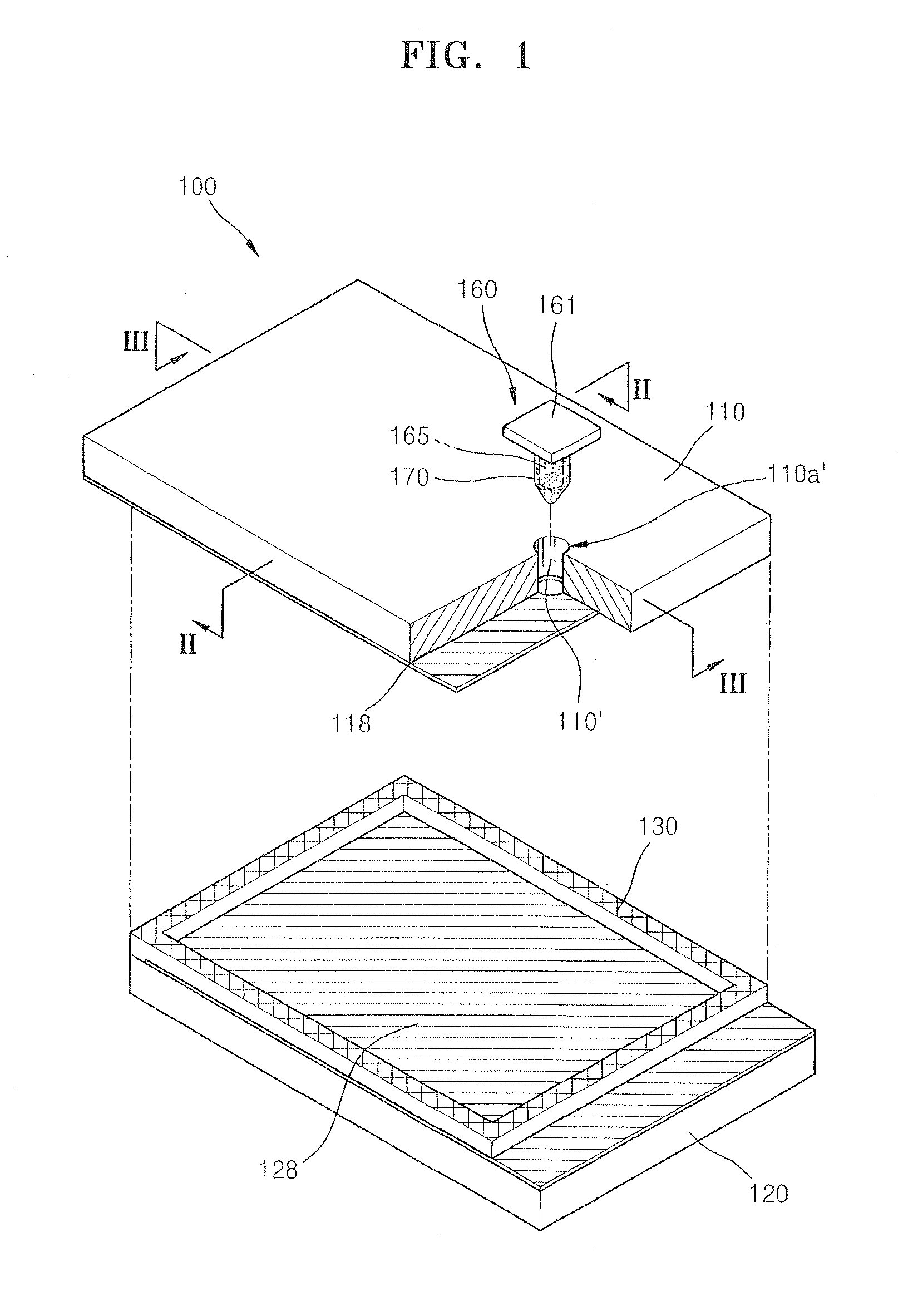
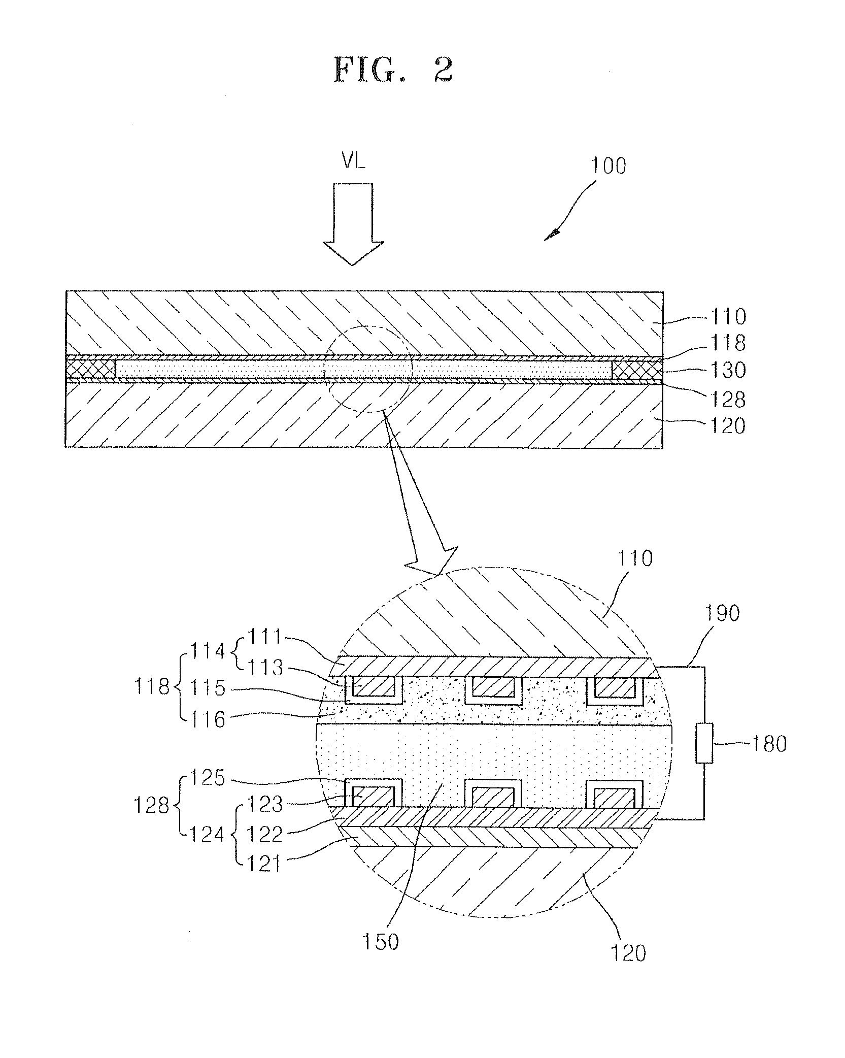
[0037]Unlike a silicon solar cell, a dye-sensitized solar cell mainly includes a photosensitive dye for receiving light having a wavelength of a visible light ray and generating excited electrons, a semiconductor material for accepting the excited electrons, and an electrolyte for reacting with electrons returning after passing through an external circuit. The dye-sensitized solar cell has a high photoelectric conversion efficiency compared to a contemporary solar cell. Thus, the dye-sensitized solar cell is expected as a next generation solar cell.

[0038]Reference will now be made in detail to embodiments, examples of which are illustrated in the accompanying drawings, wherein like reference numerals refer to the like elements throughout. In this regard, the present embodiments may have different forms and should not be construed as being limited to the descriptions set forth herein. Accordingly, the embodiments are merely described below, by referring to the figures, to explain asp...


PUM


Abstract

A photoelectric conversion device includes first and second substrates on which first and second electrodes are respectively formed, arranged to face each other, an electrolyte injected into a gap between the first and second substrates through an electrolyte injection hole formed in the first substrate, and an injection hole sealing member for sealing the electrolyte injection hole. The injection hole sealing member includes a cover portion for covering an entrance end of the electrolyte injection hole and an insertion portion extending from the cover portion along the electrolyte injection hole.

Description

CLAIM OF PRIORITY[0001]This application makes reference to, incorporates into this specification the entire contents of, and claims all benefits accruing under 35 U.S.C. §119 from an application earlier filed in the Korean Intellectual Property Office on Mar. 10, 2010, and there duly assigned Serial No. 10-2010-0021377.BACKGROUND[0002]1. Field of the Invention[0003]One or more embodiments of the present invention relate to a photoelectric conversion device and a manufacturing method thereof.[0004]2. Description of the Related Art[0005]Recently, diverse studies have been conducted regarding a photoelectric conversion device that converts light energy into electric energy. The photoelectric conversion device may be applied as one of resources to replace fossil fuels. In particular, a solar cell using solar energy has drawn wide attraction.[0006]While studies on the solar cell having a variety of driving principles are being conducted, wafer-type silicon or crystal solar cells using th...

Claims


Application Information

Patent Timeline
IPC IPC(8): H01L31/0203H01L21/02
CPCH01G9/20H01G9/2004Y02E10/542H01M14/005H01G9/2077Y02P70/50
Inventor YANG, NAM-CHOUL
Owner SAMSUNG SDI CO LTD
Why Eureka
Try Eureka