Mounting System for Hot and Cold Wall Faucets

a technology for mounting systems and faucets, which is applied in water installation, thin material handling, construction, etc., can solve the problems of increasing the time and cost of installation, damage to the interior building surface, and common problems of interior building surface damag

Active Publication Date: 2011-09-15
WCM IND INC
View PDF57 Cites 11 Cited by
  • Summary
  • Abstract
  • Description
  • Claims
  • Application Information

AI Technical Summary

Benefits of technology

[0007]It is one aspect of the present invention to provide a mounting system that supports a faucet assembly. More specifically, embodiments of the present invention employ a mounting bracket, which is adapted for interconnection to a wall member, that accommodates a faucet and an associated fluid supply line. One embodiment of the contemplated mounting system provides a stable interface between the faucet and the building surface. The bracket of embodiments of the present invention is designed to be mounted to the internal studs of a wall and thus eliminates the prior art issues associated with interconnecting a faucet directly to a building surface, such as drywall.

Problems solved by technology

Thus an installer must exercise care so not to damage the interior building surface, which increases the time and cost of installation.
Regardless of the standard of care exercised during installation, damage to the interior building surface is a common problem after installation.
More specifically, normal use of the faucet, and often an interconnected hose, generates loads on the fasteners that secure the faucet to the building surface which eventually damage the interior building surface.
Continued loading of the fasteners will eventually cause the fasteners to damage the wall surface and weaken the connection between the faucet and the interior building surface.
Ultimately, the forces may cause the faucet to dislocate from the interior building surface, perhaps permanently damaging the building surface.
As the lip is interconnected directly to the building surface, the potential for wall damage described above remains a concern.
Another drawback of the prior art mounting scheme is that the faucet handle or handles are disposed within the housing and recessed relative to the building surface and are thus difficult to access by some users.

Method used


Image

  • Mounting System for Hot and Cold Wall Faucets
  • Mounting System for Hot and Cold Wall Faucets
  • Mounting System for Hot and Cold Wall Faucets

Examples


Embodiment Construction

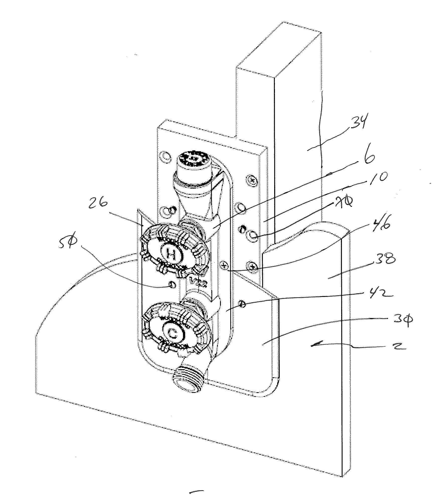
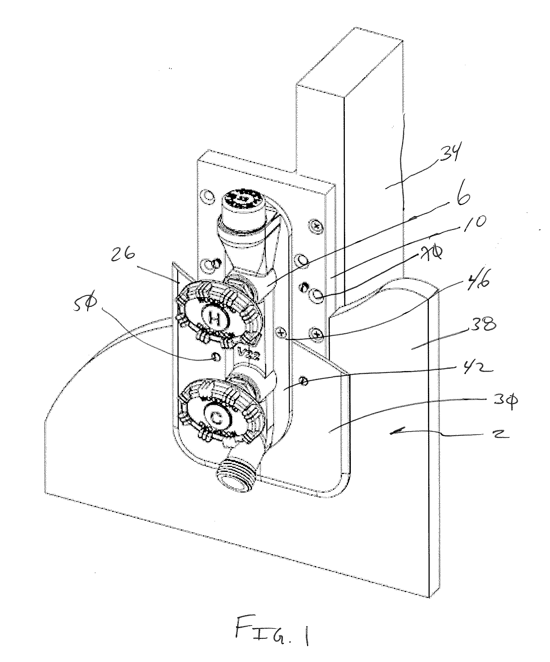
[0041]Referring to FIGS. 1-19, a faucet mounting system 2 for securing a faucet assembly 6 to a building surface 38 is provided that includes a mounting bracket 4 that receives and secures the faucet assembly 6 and associated fluid delivery tubes 18. The mounting system 2 also includes a first finishing plate 26, and a second finishing plate 30 for connecting mounting bracket 4.

[0042]Generally, the faucet mounting system 2 of various embodiments of the present invention is installed in the following manner. Initially, the desired faucet location is identified. Then, the mounting bracket 4 is interconnected to an internal building member, such as a wall stud 34, with fasteners, the fluid delivery tubes 18 of the faucet assembly 6 are passed through the mounting bracket 4, and a faucet flange 42 is interconnected to the bracket 4 with fasteners. The faucet assembly 6 is then connected to the at least one fluid delivery tube 18. After the faucet assembly 6 is pressure tested and the in...


PUM


Abstract

A system for interconnecting a faucet assembly to a wall member is provided that employs a mounting bracket for interconnection to the wall member. The mounting bracket is configured to accommodate various configurations of faucets with any number of fluid delivery tubes. The mounting system provides structural rigidity to the faucet/building interconnection while minimizing occupation of interior wall space.

Description

[0001]This application claims the benefit of U.S. Provisional Patent Application Ser. No. 61 / 312,483, filed Mar. 10, 2010, the entire disclosure of which is incorporated by reference herein. This application is also related to U.S. Published Patent No. 20090007971, filed May 5, 2008, U.S. patent application Ser. No. 29 / 333,698, filed Mar. 13, 2009, U.S. Patent Application Publication No. 20100116359, filed Dec. 29, 2009, U.S. Design Pat. No. D631,139, filed Jan. 18, 2011, U.S. Design Pat. No. D631,140, filed Jan. 18, 2011, U.S. patent application Ser. No. 29 / 383,460, filed Jan. 18, 2010, U.S. Design Pat. No. D633,988, filed Mar. 8, 2011, and U.S. Design Pat. No. D631,141, filed Jan. 18, 2011, the entire disclosures of which are incorporated by reference herein.FIELD OF THE INVENTION[0002]Embodiments of the present invention are generally related to a mounting system for securing a faucet to a building surface. More specifically, one embodiment of the present invention is a mounting ...

Claims


Application Information

Patent Timeline
Patent Type & Authority Applications(United States)
IPC IPC(8): F16L5/00
CPCE03C2001/028E03C1/042Y10T137/698Y10T137/6969Y10T137/6977
Inventor BALL, WILLIAM T.PILARCZYK, ERIC
Owner WCM IND INC
Why Eureka
Try Eureka