Apparatus and method for separating hydrophilic and hydrophobic components

a technology of hydrophilic and hydrophobic components, applied in the field of methods and apparatus for separating and/or analyzing fluids, can solve the problems of decreasing achieve the effect of reducing the likelihood of solids related damage, easy control of heat transfer, and large scal

Active Publication Date: 2012-11-29
BUCKNELL UNIVERSITY
View PDF10 Cites 8 Cited by
  • Summary
  • Abstract
  • Description
  • Claims
  • Application Information

AI Technical Summary

Benefits of technology

[0015]Among other benefits, the apparatus of the present invention operates at the milli-scale level. Milli-scale devices exhibit the fluid properties available at the microfluidic level such as mixing by diffusion, laminar flow, and easily controlled heat transfer. However, unlike microfluidic devices, milli-scale devices are able to process larger volumes of fluid while also decreasing the likelihood of solids related damage. In other words, milli-scale devices are able to retain the advantages of operating at such a small scale while exhibiting the benefits of operating at a slightly larger scale. This novel method occurs on a small scale in one embodiment, making it desirable for low volume, high value materials processing such as biomolecule extraction, particle separation, or pharmaceutical purification. These small-scale devices can readily be scaled up by running platforms of milli-fluidic devices in parallel to process larger volumes of liquids.
[0016]This extraction technique also serves as a reliable method for determining mass transfer coefficients due to the well defined interface between the two immiscible fluids.

Problems solved by technology

The use of this device for the separation of larger molecules or particles (e.g., hydrogel capsules) is of particular significance because other devices that currently achieve parallel flow of immiscible fluids use membranes or function at such small scales that they are not feasible for separation of larger molecules or particles as mentioned above.
However, unlike microfluidic devices, milli-scale devices are able to process larger volumes of fluid while also decreasing the likelihood of solids related damage.

Method used


Image

  • Apparatus and method for separating hydrophilic and hydrophobic components
  • Apparatus and method for separating hydrophilic and hydrophobic components
  • Apparatus and method for separating hydrophilic and hydrophobic components

Examples


Embodiment Construction

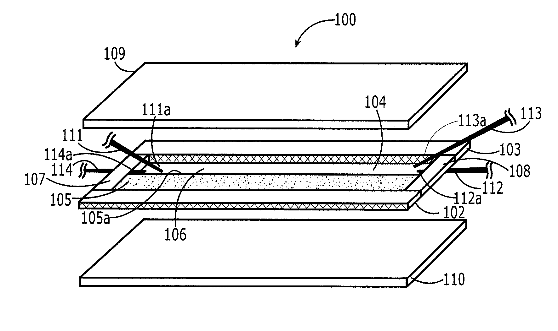
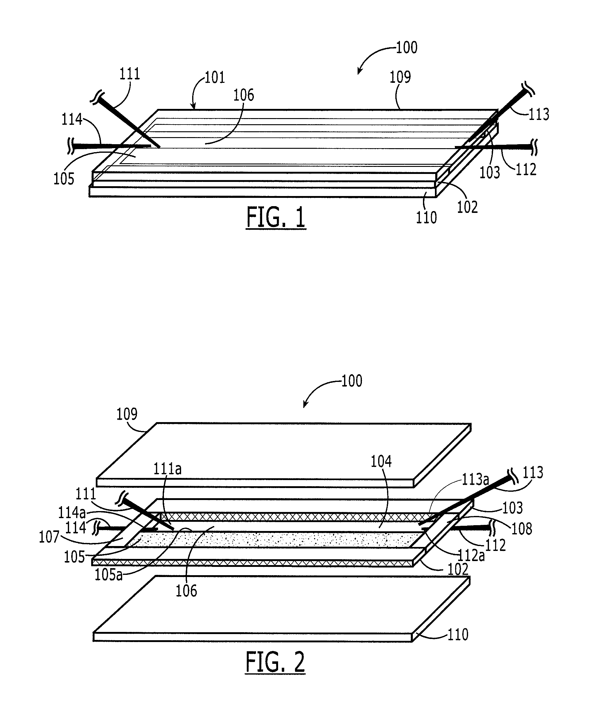
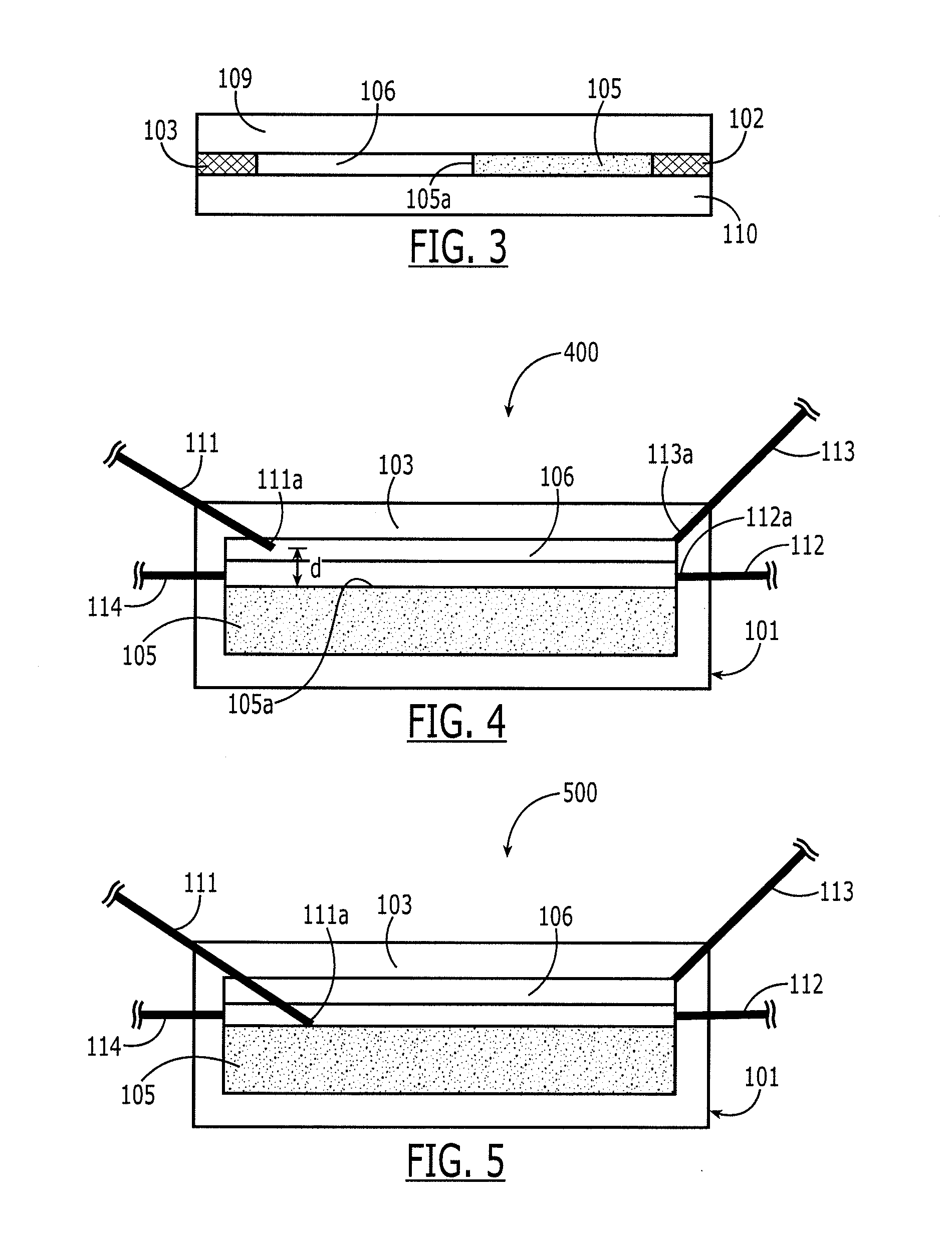
[0026]Referring to FIGS. 1-3, one embodiment of the apparatus 100 for separating hydrophilic material from hydrophobic material according to the present invention is shown. The apparatus 100 comprises at least one body 101 having at least first and second parallel walls 102, 103 defining an elongated cavity 104. Along the first wall 102 is a water-absorbing material 105 having a surface 105a essentially parallel to the second wall 103, thereby defining a channel 106 between the surface 105a and the second wall 103. The channel 106 has an upstream (left as shown) and downstream (right as shown) orientation. Disposed upstream in the channel 106 is a first inlet 111 having a first inlet end 111a disposed in the channel 106 at a certain distance d (see, e.g., FIG. 4) from the surface 105a. The first inlet 111 is configured to inject a mixture of hydrophilic and hydrophobic material into the channel. Downstream of the first inlet 111 is a first outlet 112 having a first outlet end 112a d...


PUM

PropertyMeasurementUnit
distanceaaaaaaaaaa
distanceaaaaaaaaaa
angleaaaaaaaaaa

Abstract

An apparatus for separating hydrophilic material from hydrophobic material, comprising: (a) a body having a first and second parallel walls defining an elongated cavity; (b) a water-absorbing material in the cavity along the first wall and having a surface essentially parallel to the second wall, thereby defining a channel between the surface and the second wall; (c) a first inlet having a first inlet end disposed in the channel, the first inlet being configured for injecting a mixture of hydrophilic and hydrophobic material; (d) a first outlet having a first outlet end disposed in the channel proximate the surface downstream of the first inlet end and configured for removing the hydrophilic material; and (e) a second outlet having a second outlet end disposed in the channel a distance from the surface downstream of the first inlet end and configured for removing the hydrophobic material.

Description

REFERENCE TO RELATED APPLICATION[0001]This application claims priority to U.S. Provisional Application No. 61 / 519,518, filed May 24, 2011, hereby incorporated by reference in its entirety.FIELD OF INVENTION[0002]The present disclosure relates generally to methods and apparatus for separating and / or analyzing fluids on a millifluidic scale, and, more particularly, to the formation and separation of emulsions, liquid / liquid extraction, and extraction and / or separation of molecules and particles.BACKGROUND[0003]Reliably separating fluids, such as water, oil, and gas, is critical in petroleum, medical, biological, and analytical chemistry applications, just to name a few. Separating fluids enables specific measurements to be performed on the particular fluid. For example, emulsion separation is necessary for the proper disposal of waste streams, purification in petroleum production, and the recovery of products from micro-reactors. Of particular interest in this application is the separ...

Claims


Application Information

Patent Timeline
Patent Type & Authority Applications(United States)
IPC IPC(8): B01D17/02B01D17/04
CPCB01D17/0202B01D17/02B01D17/04C02F1/44
Inventor JABLONSKI, ERIN LYNNETESFAI, JANET T.PERRY, RENEE N.MAYO, DANIEL ERIC
Owner BUCKNELL UNIVERSITY
Why Eureka
Try Eureka