
Reformer and Method of Operating the Reformer

a reformer and reformer technology, applied in the field of reformers and methods of operating reformers, can solve the problems of non-uniform injection properties, non-uniform injection properties, and non-uniform injection properties of wall-bound burners, and achieve equal or increased nox reduction, reduce capital expenses, and increase efficiency

Active Publication Date: 2011-09-15
AIR PROD & CHEM INC
View PDF18 Cites 24 Cited by
  • Summary
  • Abstract
  • Description
  • Claims
  • Application Information

AI Technical Summary

Benefits of technology

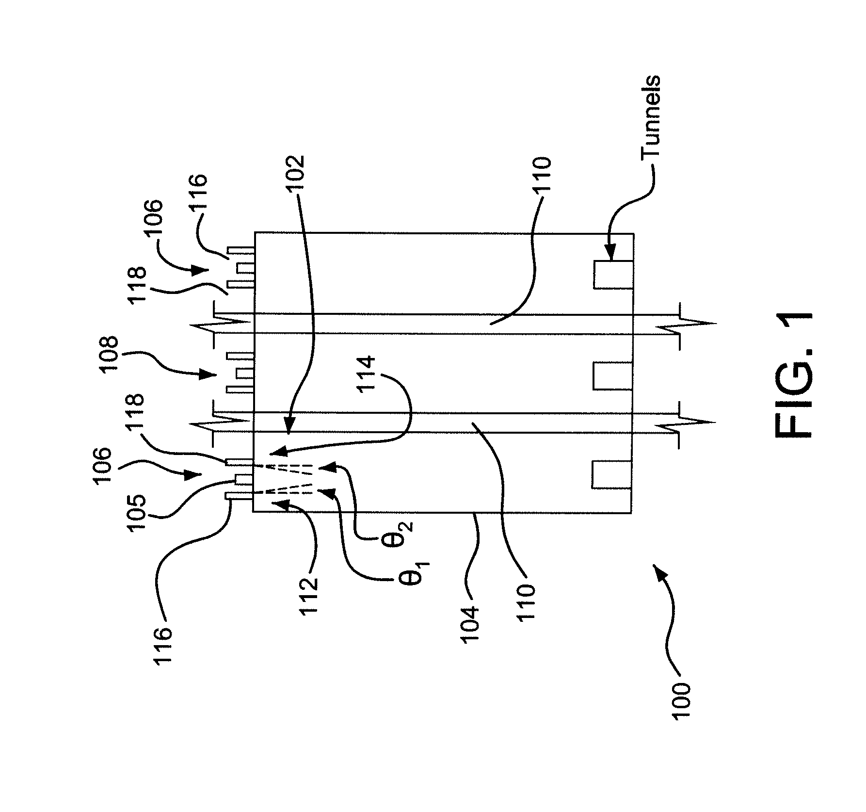
The present invention relates to a method of operating a reformer by forming non-uniform injection properties with a wall-bound burner and a non-wall-bound burner. The non-uniform injection properties provide a heat profile that increases the heat density outside the walls of the combustion region. The non-uniform properties can be formed by the flow through injectors, composition, fuel-to-oxidant ratio, oxidant flow rate, injector angle, and the number of injectors. The non-uniform properties reduce NOx generation and decrease flame volume in the combustion region, and the amount of injectors and fuel injected differ between the wall-bound and non-wall-bound burners. The invention also includes a reformer with the described features.

Problems solved by technology

The method includes combusting a fuel in a combustion region of an up-fired or down-fired reformer and forming non-uniform injection properties with a wall-bound burner.
Non-uniform injection properties are injection properties that are non-uniform.
Non-uniform injection properties are formed by the wall-bound burner.

Method used


Image

  • Reformer and Method of Operating the Reformer
  • Reformer and Method of Operating the Reformer
  • Reformer and Method of Operating the Reformer

Examples


example

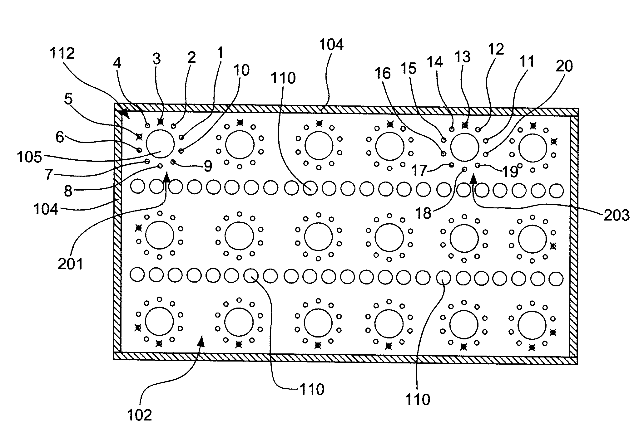
[0068]A computational fluid dynamic (CFD) models was generated. The CFD model was based upon a reformer having multiple burners, some being wall-bound burners. The wall-bound burners have less combustion space than the other burners in the furnace.

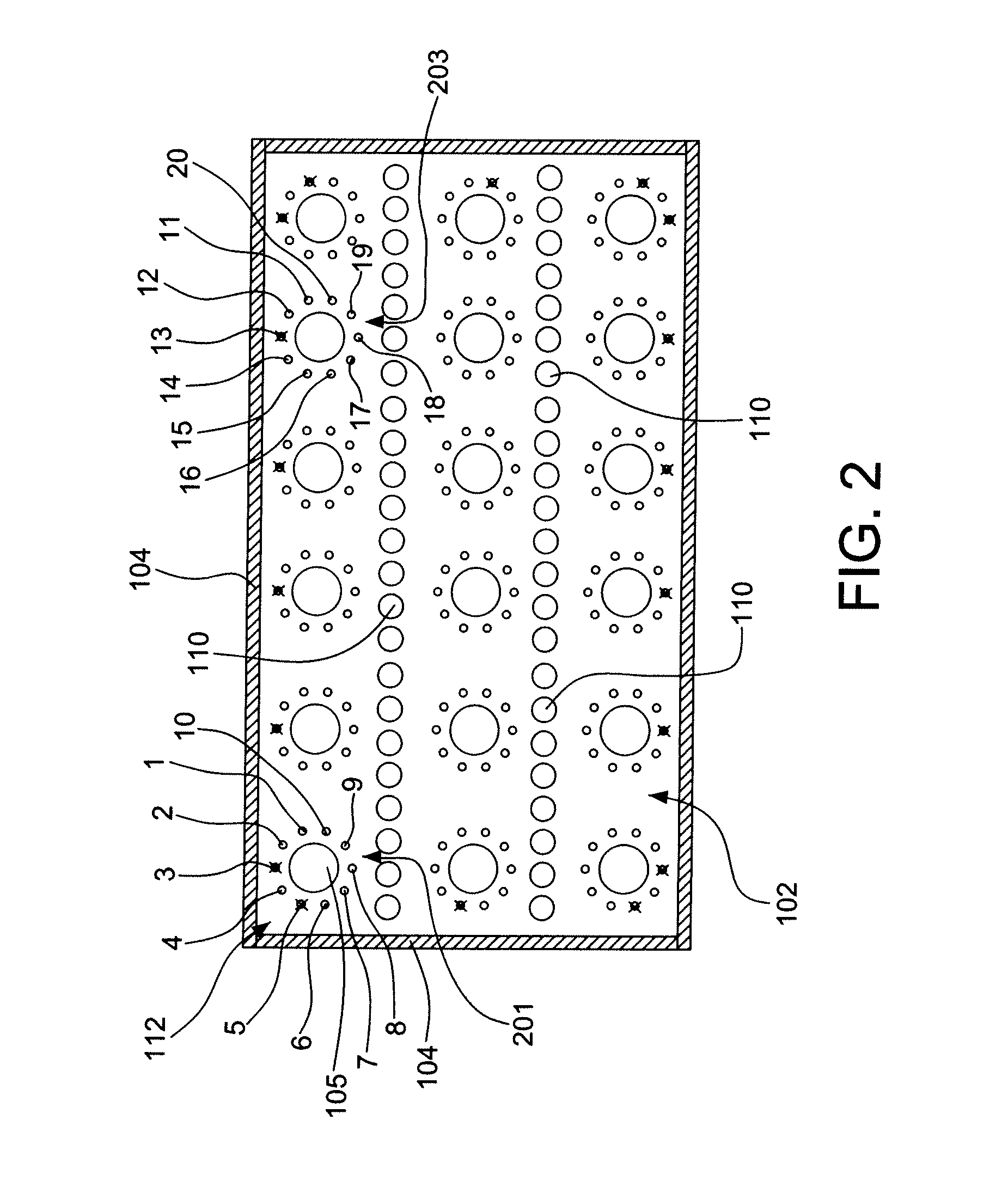
[0069]A reformer furnace was utilized with multiple rows of process tubes. Fuel injectors were removed from the wall-bound burners adjacent to a wall for a multiple process row reformer.

[0070]In the example, injector 13 (as shown in burner 203 of FIG. 2) was disabled resulting in zero flow. Injector 3 and injector 5 (as shown in burner 201 of FIG. 2) were disabled resulting in zero flow. The modification was intended to reduce furnace scale instability caused by burner-to-burner flame interaction. Such flame interaction can be measured by flame volume relative to furnace volume. The flame volume, as used in this example, is defined as regions of carbon monoxide (CO) level having at least 1000 parts per million on a wet molar basis (ppm wet...


PUM

PropertyMeasurementUnit
angle θ2aaaaaaaaaa
angle θ2aaaaaaaaaa
angle θ2aaaaaaaaaa

Abstract

A method of combustion and a reformer. The method includes combusting a fuel in combustion region of an up-fired or down-fired reformer and forming non-uniform injection properties with a wall-bound burner. The combusting is performed in a combustion region by burners, wherein at least one of the burners is the wall-bound burner forming the non-uniform injection properties. The non-uniform injection properties generate a heat profile providing a first heat density proximal to a wall and a second heat density distal from the wall, the second heat density being greater than the first heat density. The non-uniform injection properties are formed by injection properties selected from an angle of one or more injectors, a flow rate of one or more injectors, an amount and / or location of oxidant injectors, an amount and / or location of fuel injectors, and combinations thereof.

Description

BACKGROUND[0001]In furnaces having multiple rows of burners, such as reforming furnaces or reformers, burners positioned in close proximity to walls and / or corners of the furnace perform differently than burners positioned distal from walls and / or corners of the furnace. Generally, in comparison to burners positioned distal from the walls and / or corners of the furnace, burners positioned in close proximity to walls and / or corners of the furnace interact with the wall of the furnace more and produce greater amounts of NOx.[0002]Great Britain patent GB2071832, which is hereby incorporated by reference in its entirety, discloses a furnace and the operation thereof. Specifically, the GB2071832 patent discloses furnace level air staging in a boiler. Generally, the burners in the boiler are provided with combustion air that is much less than stoichiometric (about 60% to about 80% of stoichiometric), and the remaining combustion air is provided by ports in the furnace away from the boilers...

Claims


Application Information

Patent Timeline
Patent Type & Authority Applications(United States)
IPC IPC(8): C01B3/38B01J19/00
CPCB01J2208/00504F23D14/84F23C2900/03002F23C5/08
Inventor HENDERSHOT, REED JACOBLI, XIANMING JIMMYSLAVEJKOV, ALEKSANDAR GEORGI
Owner AIR PROD & CHEM INC
Learn More