Optical transmission apparatus for visible light communication

a transmission apparatus and optical transmission technology, applied in the direction of transmission monitoring, transmission monitoring/testing/fault measurement system, close-range type system, etc., can solve the problems of poor power conversion efficiency, difficult to implement data communication at a high speed of several or higher mhz, and conventional technology cannot work with optical transmission apparatus based on linear drive method, etc., to achieve excellent power conversion efficiency, increase power conversion efficiency, and high power conversion efficiency

Inactive Publication Date: 2011-09-15
KOOKMIN UNIV IND ACAD COOP FOUND
View PDF5 Cites 39 Cited by
  • Summary
  • Abstract
  • Description
  • Claims
  • Application Information

AI Technical Summary

Benefits of technology

[0012]Another object of the present invention is to provide an optical transmission apparatus for visible light communication which adopts a switching drive method, thereby providing high power conversion efficiency.
[0013]Still another object of the present invention is to provide an optical transmission apparatus for visible light communication which is equipped with an inexpensive high-capacity drive circuit having excellent power conversion efficiency and device heat emission characteristics.
[0014]Still another object of the present invention is to provide an optical transmission apparatus for visible light communication which is capable of increasing power conversion efficiency, thus contributing to energy conservation, which is an important current social issue.

Problems solved by technology

However, because of the slow dynamic characteristics of the switching mode DC / DC converter, the bandwidth of the switching drive method is several tens of kHz, and is too small to selectively turn on and off LED current at a high speed to perform data communication while maintaining the magnitude of the LED current at a constant value, so that it is disadvantageous in that when it is applied to visible light communication, it is difficult to implement data communication at a high speed of several or higher MHz.
In spite of the existence of the switching drive method capable of providing high power conversion efficiency, the conventional technology cannot work with an optical transmission apparatus based on a linear drive method because the above-described disadvantages cannot be overcome.
The linear drive-type circuit has the advantage of implementing high-speed data communication in such a way that the power conversion unit outputs a constant DC voltage and the drive unit operates a drive element, such as a switch, in a linear region, but has the disadvantage of having poor power conversion efficiency and poor drive element heat emission characteristics because current flows through LED lamps while the operating voltage is always being applied to the drive element which sends signals to the LED lamps, so that the manufacturing cost thereof is high and it is not suitable for high-capacity drive circuits.
Since the linear drive method cannot accurately control luminance and the switching drive method cannot control the peak value of current flowing through the LED lamps, the two drive methods have problems with the output of such luminance and also have problems with life span and reliability.

Method used


Image

  • Optical transmission apparatus for visible light communication
  • Optical transmission apparatus for visible light communication
  • Optical transmission apparatus for visible light communication

Examples


Embodiment Construction

[0030]Reference now should be made to the drawings, in which the same reference numerals are used throughout the different drawings to designate the same or similar components.

[0031]The configuration and operation of the embodiments of the present invention will be described below with reference to the accompanying drawings.

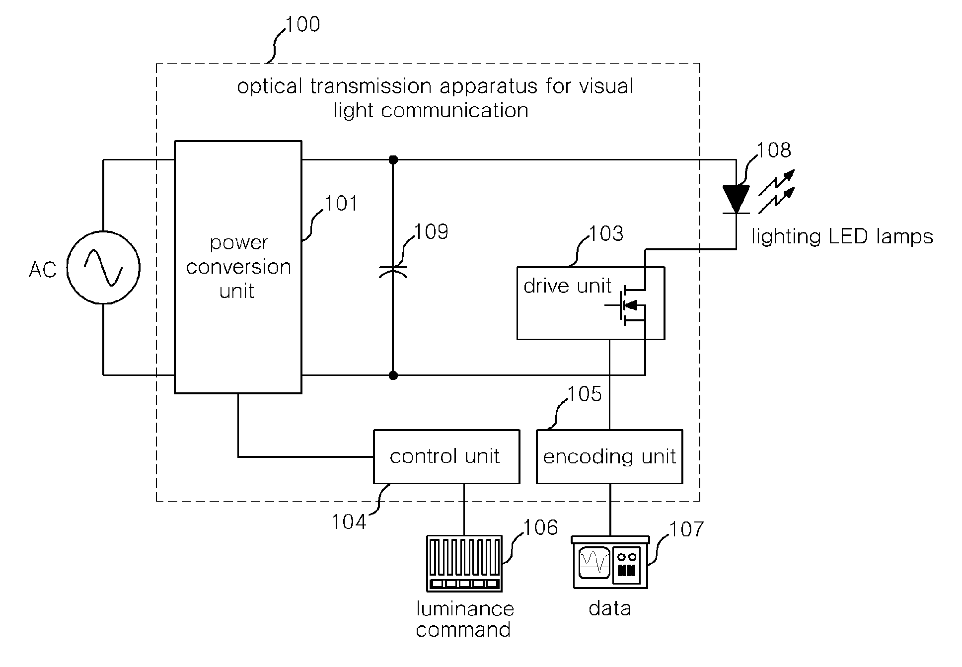
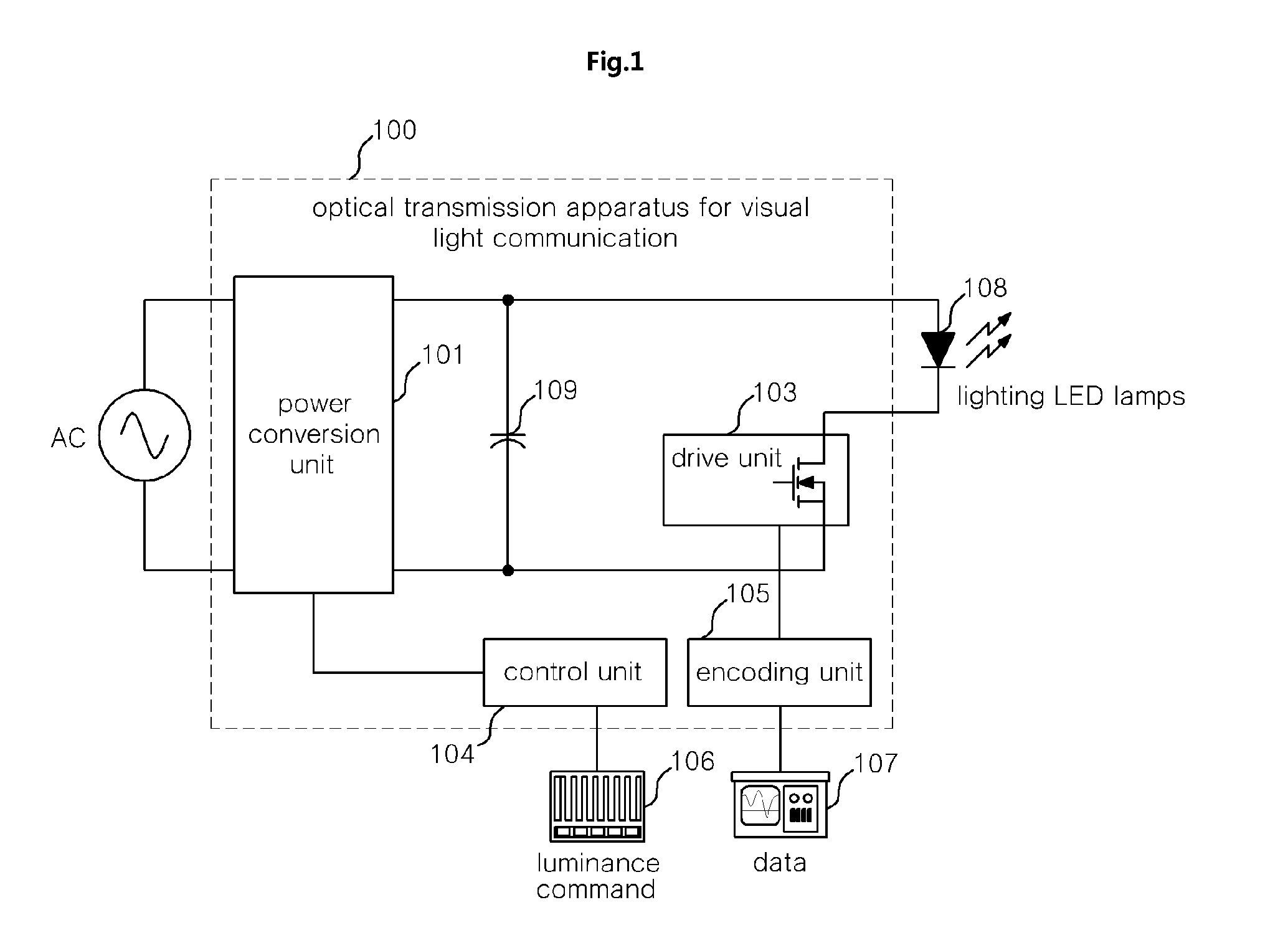
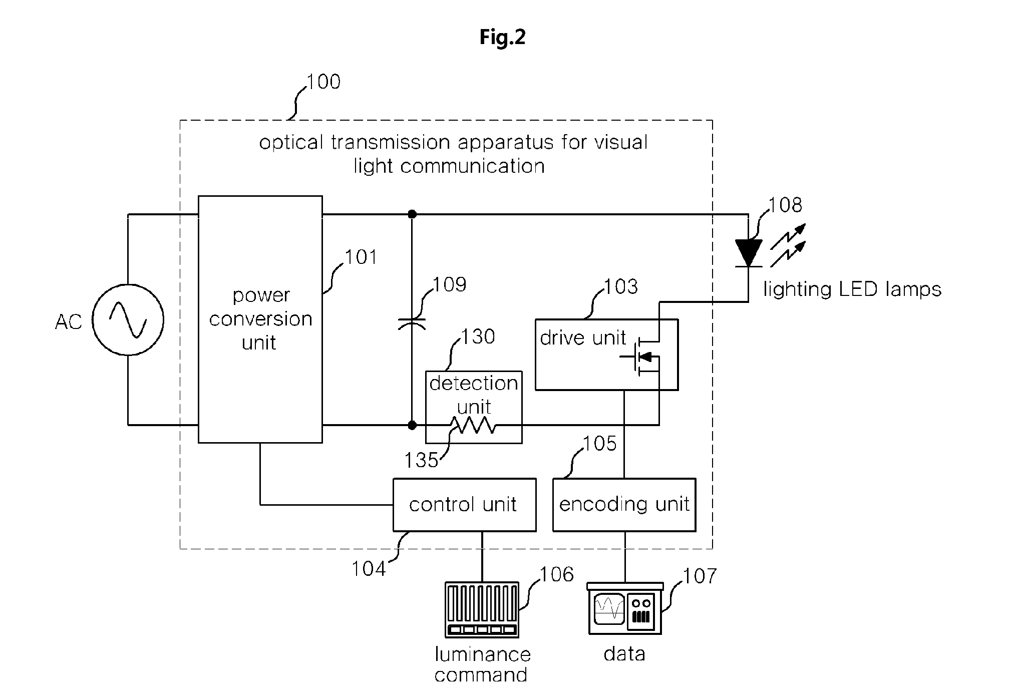
[0032]FIG. 1 is a block diagram of an optical transmission apparatus for visible light communication according to the present invention, FIG. 2 is a block diagram of a first embodiment of the optical transmission apparatus for visible light communication shown in FIG. 1, and FIG. 3 is a block diagram of a second embodiment of the optical transmission apparatus for visible light communication shown in FIG. 1.

[0033]As shown in FIG. 1, the optical transmission apparatus for visible light communication according to the present invention includes a power conversion unit 101, a drive unit 103, an encoding unit 105, and a control unit 104. The power conversion unit 101 ...


PUM


Abstract

Disclosed herein is an optical transmission apparatus for visible light communication. The optical transmission apparatus includes a power conversion unit, a drive unit, an encoding unit, a control unit, and a detection unit. The power conversion unit provides Direct Current (DC) power to the lighting LED lamps. The drive unit is operated using a switching drive method and supplies operating current to the lighting LED lamps. The encoding unit is connected to an external network, receives and encodes data, and provides it to the drive unit. The control unit controls the operation of the power conversion unit, the drive unit, and the encoding unit. The detection unit measures the strength of a visible light signal sent by the lighting LED lamps.

Description

CROSS-REFERENCE TO RELATED APPLICATION[0001]This application claims priority to and the benefit of Korean Patent Application No. 10-2010-0022396 filed in the Korean Intellectual Property Office on Mar. 12, 2010, the entire contents of which are incorporated herein by reference.BACKGROUND OF THE INVENTION[0002]1. Field of the Invention[0003]The present invention relates generally to an optical transmission apparatus for visible light communication using a plurality of Light-Emitting Diode (LED) lamps, and, more particularly, to an optical transmission apparatus for visible light communication which enables high-speed data communication and provides high power conversion efficiency.[0004]2. Description of the Related Art[0005]Recently, as the light emission efficiency of Light-Emission Diodes (LEDs) has improved and the prices thereof have decreased, LEDs have been popularized not only in the special illumination fields of portable devices, displays, automobiles, signal lights and bil...

Claims


Application Information

Patent Timeline
Patent Type & Authority Applications(United States)
IPC IPC(8): H04B17/00
CPCH04B10/116H04B10/1149
Inventor HAN, SANG-KYOOHONG, SUNG-SOOJANG, BYUNG-JUNROH, CHUNG-WOOK
Owner KOOKMIN UNIV IND ACAD COOP FOUND
Why Eureka
Try Eureka