Surgical Instrument

a surgical instrument and instrument body technology, applied in the field of surgical instruments, can solve the problems of inability to release bone punches from patients, inability to use other instruments, and inability to meet the needs of patients,

Active Publication Date: 2011-09-15
AESCULAP AG
View PDF14 Cites 12 Cited by
  • Summary
  • Abstract
  • Description
  • Claims
  • Application Information

AI Technical Summary

Benefits of technology

[0025]In this case, it may also be of advantage when the predetermined state of residual charge can be adjusted. The use of the ...

Problems solved by technology

The energy capacity is necessarily limited in the case of such instruments, with the risk that operating processes can no longer be finished when the charge capacity is exhausted.
This is a problem, in particular, in the case of operations which relate to the central nervous system when the instruments are used to remove, for example, bones or tissue material from the patient with a considerable use of force, for example with so-called bone punches.
The problem for the surgeon is then that the bone punch cannot be released from the patient and replaced by another instrument ready for use.
The space for accommodating the energy storage device is considerably restricted as a result.
A permanent connection to an external energy source is also not desirable from an ergonomic point of view.
In many cases, operations do, however, require a supply of energ...

Method used


Image

  • Surgical Instrument
  • Surgical Instrument
  • Surgical Instrument

Examples


Embodiment Construction

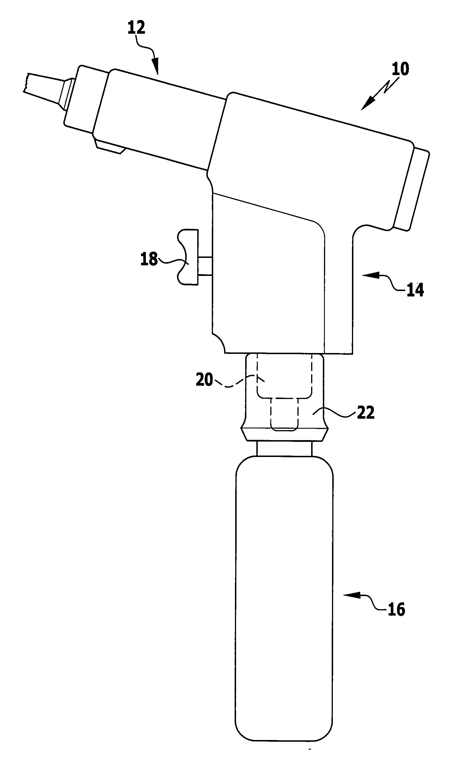
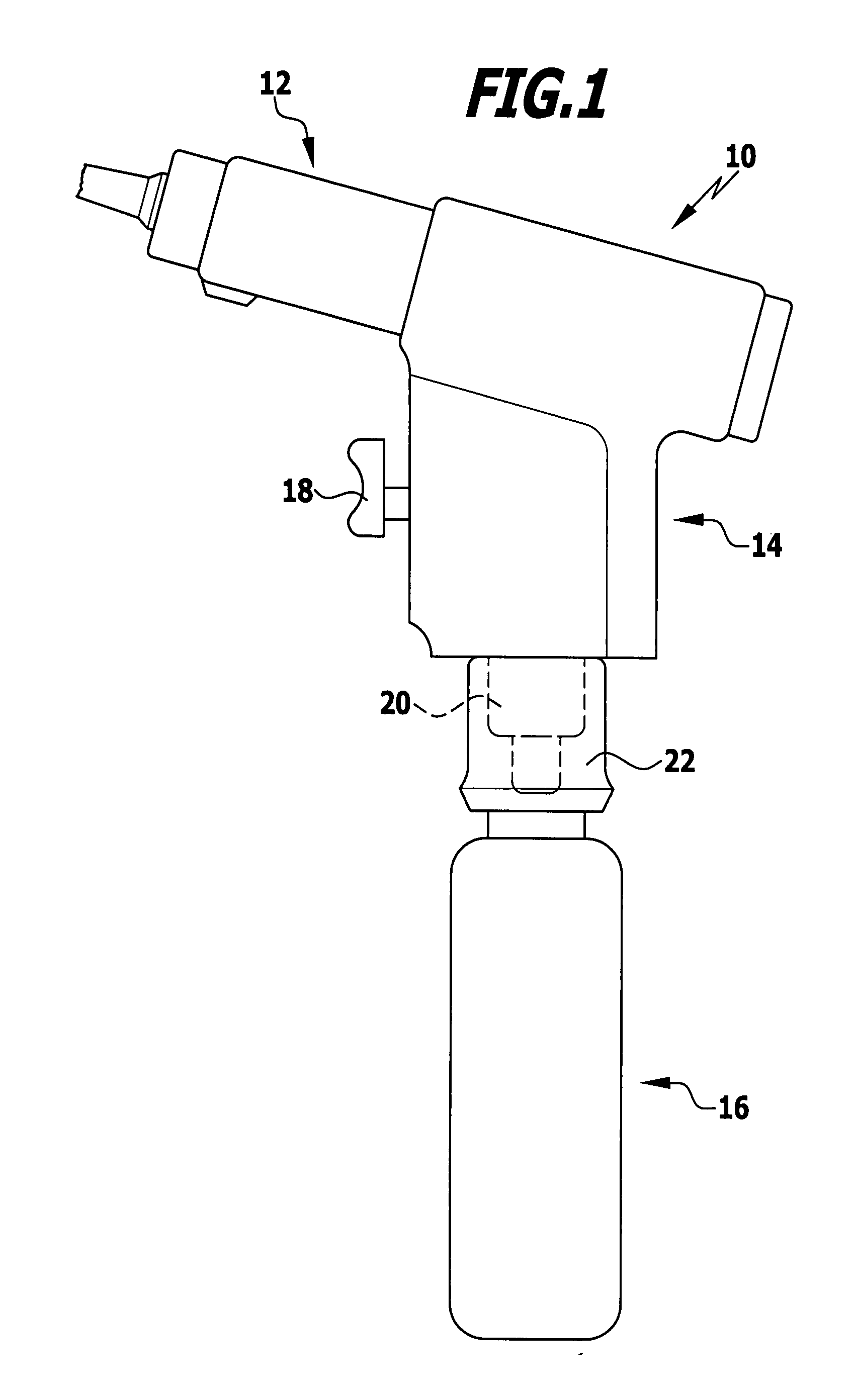
[0050]FIG. 1 shows an instrument according to the invention in the form of a pneumatically driven clip applier 10 with an operating device 12 (shown only partially) designed as an applier, a handle 14 as well as an energy storage device in the form of a gas cartridge 16.

[0051]The clip applier 10 comprises a compressed gas drive (not shown) which is arranged in its handle 14 and actuates the applier mechanism. The clip applier 10 is controlled via a push-button switch 18 which projects out of the handle 14 which is preferably in the shape of a pistol.

[0052]A connection flange 20 which can be releasably connected to the gas cartridge 16 protrudes at the lower end of the handle 14. For the connection to the handle 14, the gas cartridge 16 has a short connection piece 22, with which the gas cartridge 16 can be connected to the connection flange 20 of the handle in a gas-tight manner.

[0053]With respect to the details of the gas-tight connection between handle 14 and gas cartridge 16, att...


PUM


Abstract

In order to further develop a surgical instrument with an energy-driven operating device, an energy storage device as well as a control device for driving the operating device as required and supplying it with energy from the energy storage device such that an optimum utilization of the capacity of the energy storage device is achieved without any risk for the surgeon or the patient, in particular in view of the different energy requirements of the individual operating processes, it is suggested that when a predetermined state of residual charge of the energy storage device is reached and/or it is fallen below for the first time the control device make its residual charge available for returning the tool into a rest position.

Description

[0001]This application claims the benefit of German Patent Application No. 10 2010 012 011.1 filed on Mar. 12, 2010.[0002]The present disclosure relates to the subject matter disclosed in German application number 10 2010 012 011.1 of Mar. 12, 2010, which is incorporated herein by reference in its entirety and for all purposes.BACKGROUND OF THE INVENTION[0003]The invention relates to a surgical instrument with an energy-driven operating device, an energy storage device as well as a control device for operating the operating device as required and supplying it with energy from the energy storage device.[0004]Instruments of this type are known with an operating device which is driven electrically or pneumatically. Accumulators or batteries or rather gas cartridges serve as energy storage devices.[0005]The energy capacity is necessarily limited in the case of such instruments, with the risk that operating processes can no longer be finished when the charge capacity is exhausted.[0006]T...

Claims


Application Information

Patent Timeline
IPC IPC(8): A61B17/00
CPCA61B17/1285A61B17/1611A61B2017/00734A61B17/1628A61B2017/00548A61B17/1626
Inventor SCHULZ, PETERNESPER, MARKUSWEISSHAUPT, DIETERFAULHABER, KONSTANTIN
Owner AESCULAP AG
Why Eureka
Try Eureka