
Method for measuring scattering absorber and device for measuring scattering absorber

Active Publication Date: 2011-09-15
HAMAMATSU PHOTONICS KK
View PDF2 Cites 3 Cited by
  • Summary
  • Abstract
  • Description
  • Claims
  • Application Information

AI Technical Summary

Benefits of technology

[0013]According to the present invention, it is possible to acquire a theoretical waveform in which the influence of an instrumental function is eliminated from a measurement waveform of a scattering medium which is a measurement object without using the instrumental function. Further, the theoretical waveform of the scattering medium which is the measurement object is given as a previously available function with a predetermined parameter. Thereby, even where noise is contained in the measurement waveform, it is possible to obtain the theoretical waveform of the scattering medium which is the measurement object more accurately. Therefore, according to the present invention, even where noise is contained in the measurement waveform, it is possible to acquire the internal information of the scattering medium more accurately and easily, with the influence of an instrumental function taken into account.

Problems solved by technology

Therefore, this method poses a problem that prolongs the working time and measurement time.

Method used


Image

  • Method for measuring scattering absorber and device for measuring scattering absorber
  • Method for measuring scattering absorber and device for measuring scattering absorber
  • Method for measuring scattering absorber and device for measuring scattering absorber

Examples


Embodiment Construction

[0021]Hereinafter, a detailed description will be made for a preferred embodiment of the method for measuring a scattering medium and the apparatus for measuring a scattering medium in the present invention by referring to the drawings. In description of the drawings, the same components are given the same reference numerals, and overlapping description will be omitted. It is noted that the dimensional ratio given in the drawings is not necessarily in agreement with that referred to in the description.

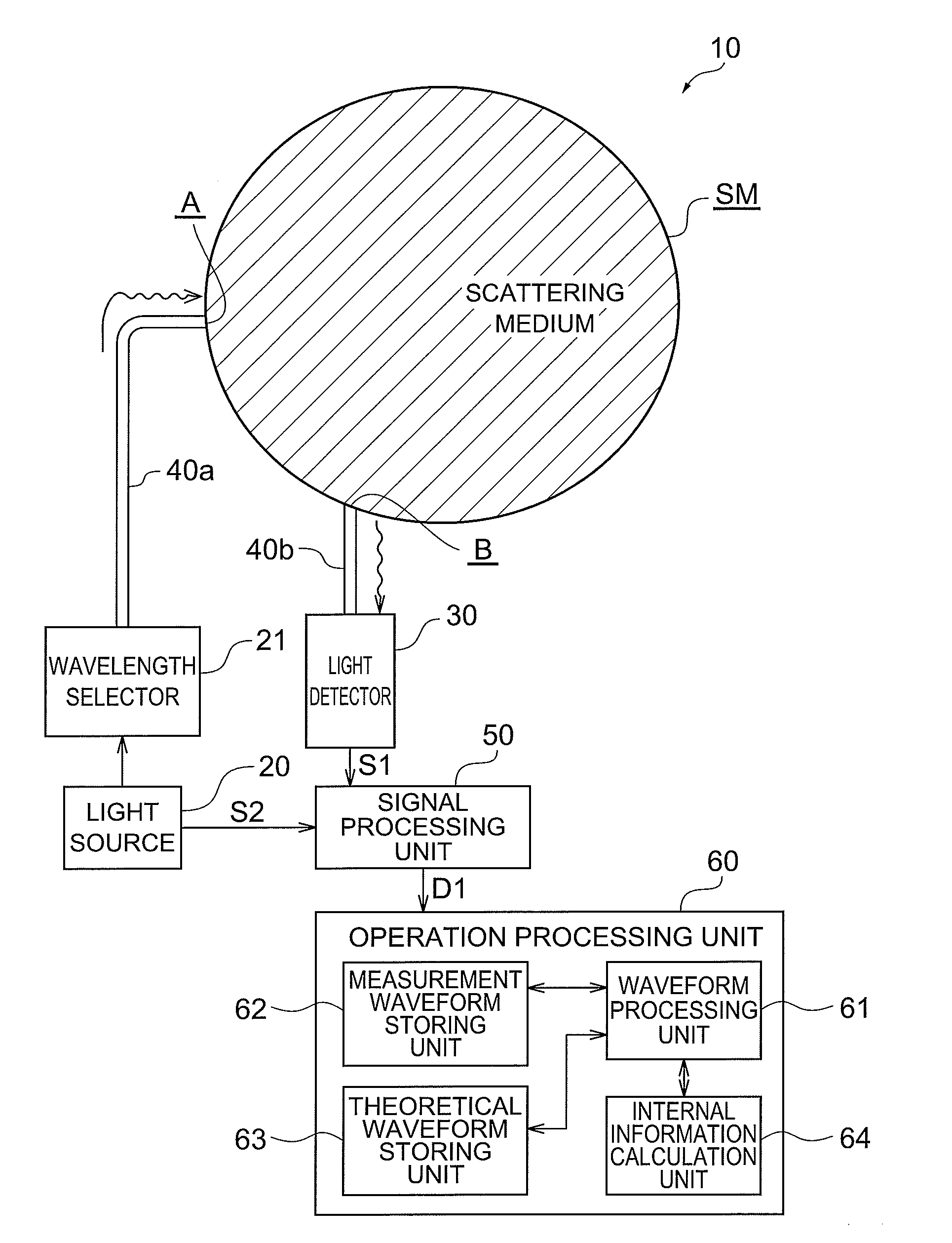
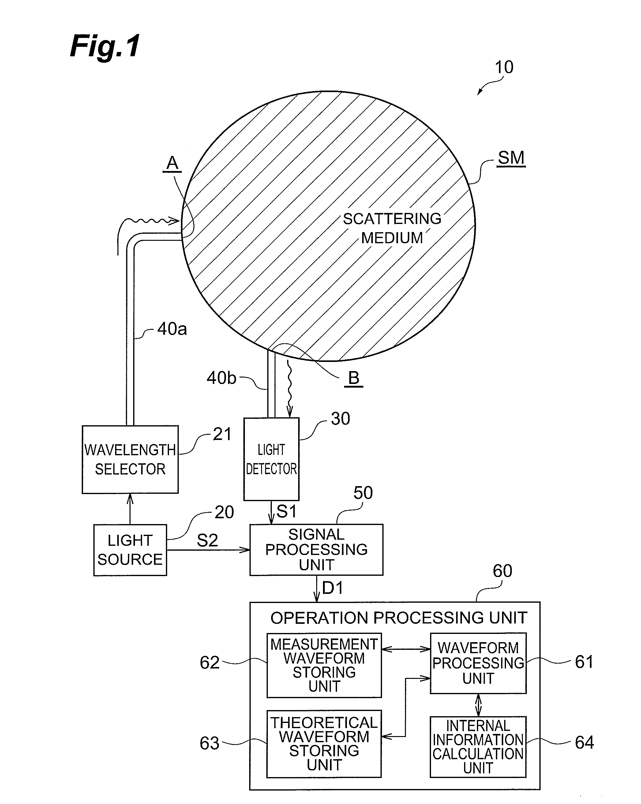
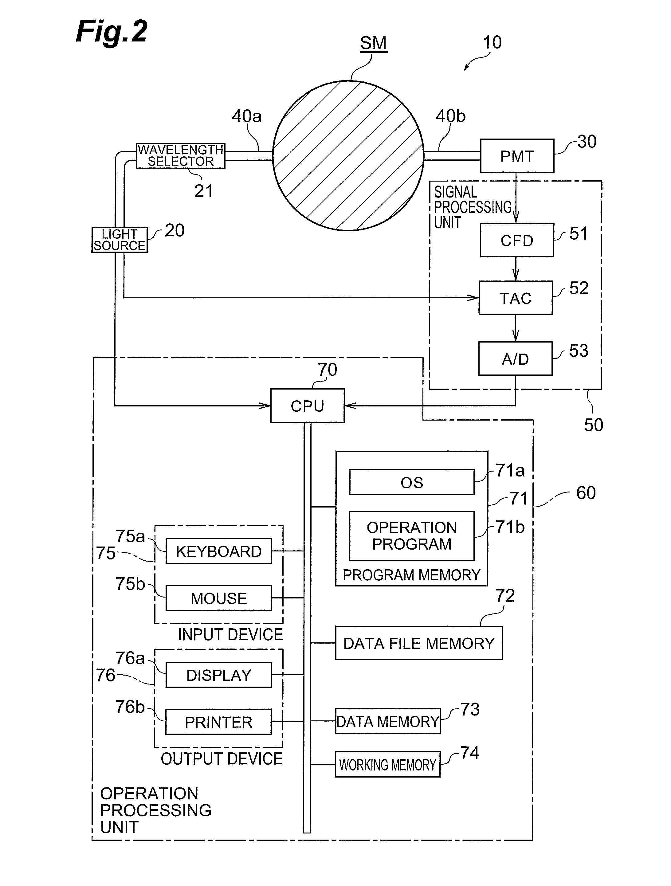
[0022]FIG. 1 shows a functional configuration of an apparatus 10 for measuring a scattering medium of the present embodiment. FIG. 2 shows a hardware configuration of the apparatus 10 for measuring a scattering medium of the present embodiment. The apparatus 10 for measuring a scattering medium is an apparatus for measuring the internal information of a scattering medium. A scattering medium which is a measurement object of the apparatus 10 for measuring a scattering medium is to scatt...


PUM


Abstract

Acquired is the internal information of a scattering medium more accurately and easily, with the influence of an instrumental function taken into account, even where noise is contained in a measurement waveform.In a method for measuring a scattering medium, pulse light with a predetermined wavelength is made incident on a scattering medium which is a measurement object and a scattering medium for reference (S01b, S02b), the pulse light transmitted inside each of the scattering media is detected to acquire a light detection signal (S01c, S02c), the measurement waveform is acquired on the basis of the detected light detection signal (S01d, S02d), a parameter of a function showing the theoretical waveform of the measurement object is specified in such a manner that the result of convolution operation on the theoretical waveform of the measurement object and the measurement waveform of the reference is made equal to the result of convolution operation on the theoretical waveform of the reference and the measurement waveform of the measurement object (S03), and calculation is made for the internal information of the scattering medium on the basis of the theoretical waveform shown by the function (S04).

Description

TECHNICAL FIELD[0001]The present invention relates to a method for measuring a scattering medium and an apparatus for measuring a scattering medium in order to measure the internal information of scattering media such as a living body, etc.BACKGROUND ART[0002]As an apparatus for measuring the internal information of a scattering medium such as a living body, an apparatus which uses pulse light transmitted inside the scattering medium, for example, an apparatus for measuring a scattering medium by using time resolved spectroscopy (TRS) such as an optical mammography apparatus is available. A time-resolved waveform of light measured by the above-described apparatus includes not only response time characteristics of a scattering medium which is a measurement object but also response time characteristics (instrumental function) of the apparatus itself. Therefore, in carrying out an analysis of data, it is necessary to eliminate the influence of the instrumental function from a measureme...

Claims


Application Information

Patent Timeline
IPC IPC(8): G06F19/00
CPCA61B5/0091A61B5/0059G01N21/4795A61B5/4312
Inventor YOSHIMOTO, KENJIOHTA, KAZUYOSHIYAMASHITA, DAISUKESUZUKI, HIROAKI
Owner HAMAMATSU PHOTONICS KK
Learn More