Overhead protection system

Inactive Publication Date: 2011-09-22
RECON INT FZE
View PDF13 Cites 10 Cited by
  • Summary
  • Abstract
  • Description
  • Claims
  • Application Information

AI Technical Summary

Benefits of technology

[0006]The present invention provides the needed alternative. A protective structure designed to be built around an existing, unhardened structure is disclosed. This retrofit approach is cost-effective, easy to build, and relatively quick to construct. It does not require any change to the existing structure, and in many cases, will allow operation and use of the existing structure to continue without interruption during construction. This latter benefit is important, particularly if the facility being retrofitted is involved in active operations against an enemy threat.
[0007]The invention has a support frame that is built outside the existing structure. A blast cover, made of pre-formed concrete panels in a preferred embodiment, is supported by the support frame. The invention is limited in size because the blast cover is heavy and requires substantial support. If the structure is too wide, it is difficult to

Problems solved by technology

The nature of the threat level often changes, making it difficult to have the proper type of protective structures in place at all locations.
In some instances, facilities originally built by one government or force are taken over by another, and the facilities may not have sufficient protection given the new threat levels faced.
When this happens, the government or other entity operating the facilities must make difficult decisions.
That, however, may leave the force unable to respond to the threat in an effective manner.
That is a very expensive and time-consuming approach, but it does yield good results in terms of protecting the force and keeping the force where it needs to be.
If these hangers were not built to withstand the blast of incoming ordinance, they will be at r

Method used


Image

  • Overhead protection system
  • Overhead protection system
  • Overhead protection system

Examples


Embodiment Construction

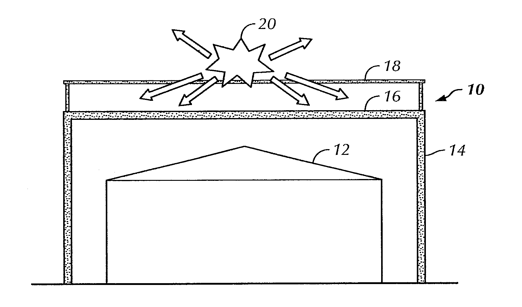
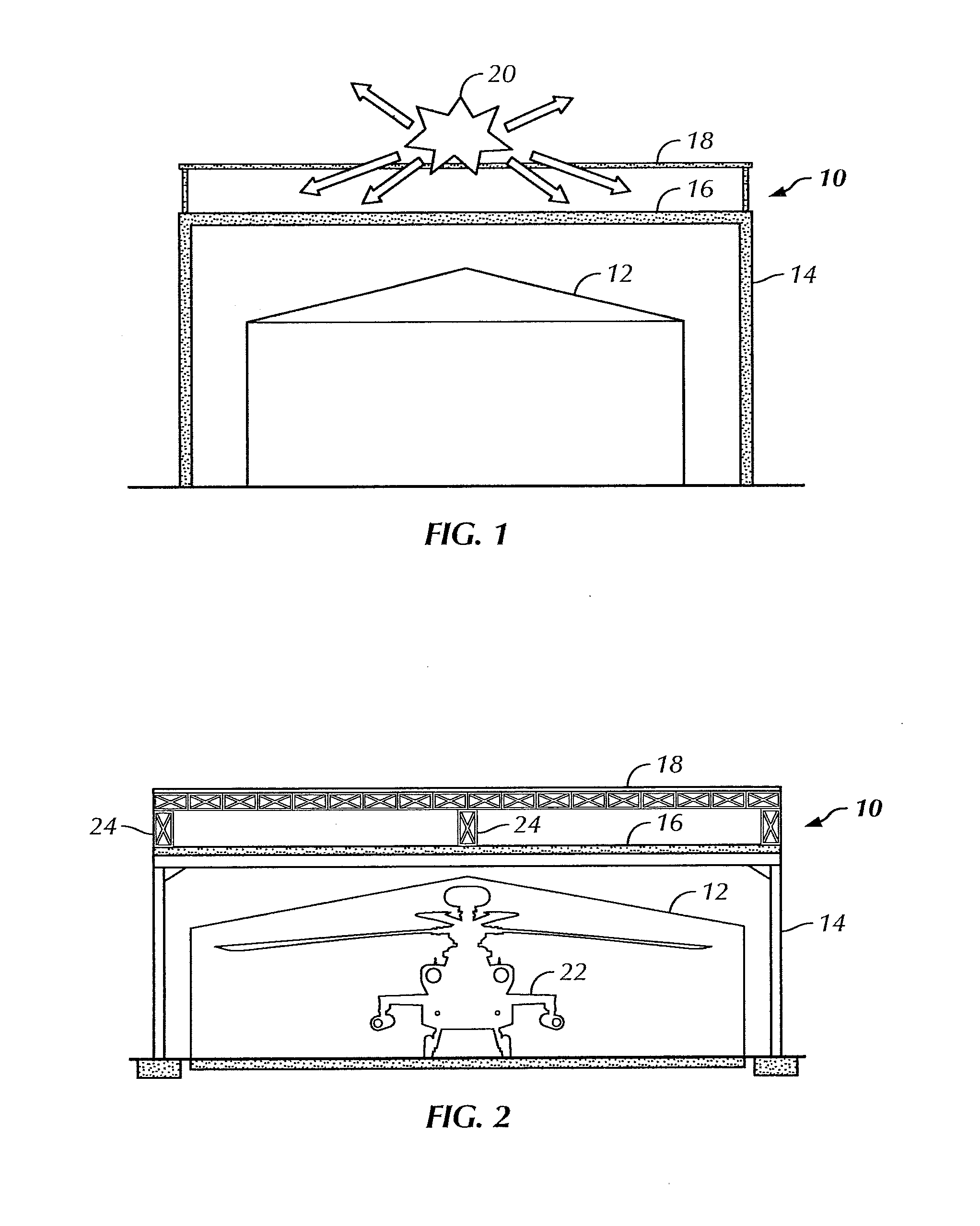
[0019]Turning to the figures, the present invention can be best understood by starting with a functional diagram. In FIG. 1, a block diagram illustrates the basic structure and purpose of the present invention. A protective structure 10 is shown built around an existing, unhardened structure 12. A lower support frame 14 is shown supporting a blast cover 16 and burster screen 18. Incoming ordinance 20 is shown just making contact with the burster screen 18. This contact causes the ordinance 20 to detonate.

[0020]The burster screen 18 is positioned about 1-3 meters above the blast cover 16 in a preferred embodiment. The shrapnel, blast wave, and heat created by the detonation of the ordinance 20 dissipates somewhat before making contact with the blast cover 16. These destructive forces are deflected and absorbed by the blast cover 16, and the existing, unhardened structure 12, is thus protected from the incoming ordinance. The particular structural components of the preferred embodimen...


PUM


Abstract

A protective shelter is disclosed. The shelter may be sized to protect an existing, unhardened structure, and its contents. Or, the shelter may be sized to protect an individual or other objects of similar size. In either case, the shelter provides protection from blasts from explosive shells, rockets, and the like. The shelter has a support frame that supports a blast cover that is positioned above the object or objects to be protected. A burster screen is positioned above the blast cover and may be supported by the support frame. The burster screen serves to detonate incoming ordinance before the ordinance reaches the protected object or objects. The blast cover is strong enough to withstand the resulting shock from the detonated ordinance, and thus prevents damage to the protected object or objects located below the protective shelter. This invention may be used to retrofit existing, unhardened structures in areas where additional protection is needed. It also may be used as part of the design of new facilities, and offers the option to later remove the hardened, protective part of the structure if the threat level changes for the better. In the smaller, personnel-protection embodiment, the invention may be air dropped to remote locations and assembled by personnel in the field.

Description

FIELD OF THE INVENTION[0001]The invention relates to a protective structure, and in particular to a protective structure built to protect another structure or personnel from harm caused by blasts resulting from explosive shells, rockets, and the like.BACKGROUND AND SUMMARY OF THE INVENTION[0002]Terrorism, war, and other hostile situations are regrettably common around the world. The nature of the threat level often changes, making it difficult to have the proper type of protective structures in place at all locations. For example, military facilities in some locations are built with a relatively low level of hardening because the threat level in the area was not particularly high when the facilities were constructed, or for other reasons. In some instances, facilities originally built by one government or force are taken over by another, and the facilities may not have sufficient protection given the new threat levels faced.[0003]When this happens, the government or other entity ope...

Claims


Application Information

Patent Timeline
IPC IPC(8): E04H9/04E04H12/00E04G21/14
CPCE04H9/12E04H9/04
Inventor SMITH, BRIAN
Owner RECON INT FZE
Why Eureka
Try Eureka