Method of controlling the centre of gravity of an aircraft

Active Publication Date: 2011-09-22
AIRBUS OPERATIONS LTD
View PDF11 Cites 13 Cited by
  • Summary
  • Abstract
  • Description
  • Claims
  • Application Information

AI Technical Summary

Benefits of technology

[0006]According to an aspect of the present invention there is provided a method of controlling the centre of gravity of an aircraft having a plurality of fuel tanks, the method comprisi

Problems solved by technology

If the GWCG is allowed to move beyond certain limits the ability of the pilot to control the aircraft can be impaired.
However, in the event of a failure of one or more of the FQIs, and in particular the FQI

Method used


Image

  • Method of controlling the centre of gravity of an aircraft
  • Method of controlling the centre of gravity of an aircraft
  • Method of controlling the centre of gravity of an aircraft

Examples


Embodiment Construction

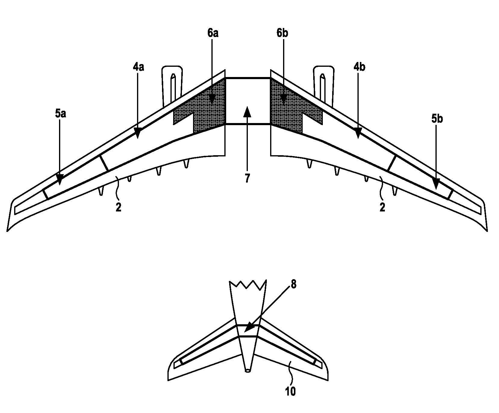
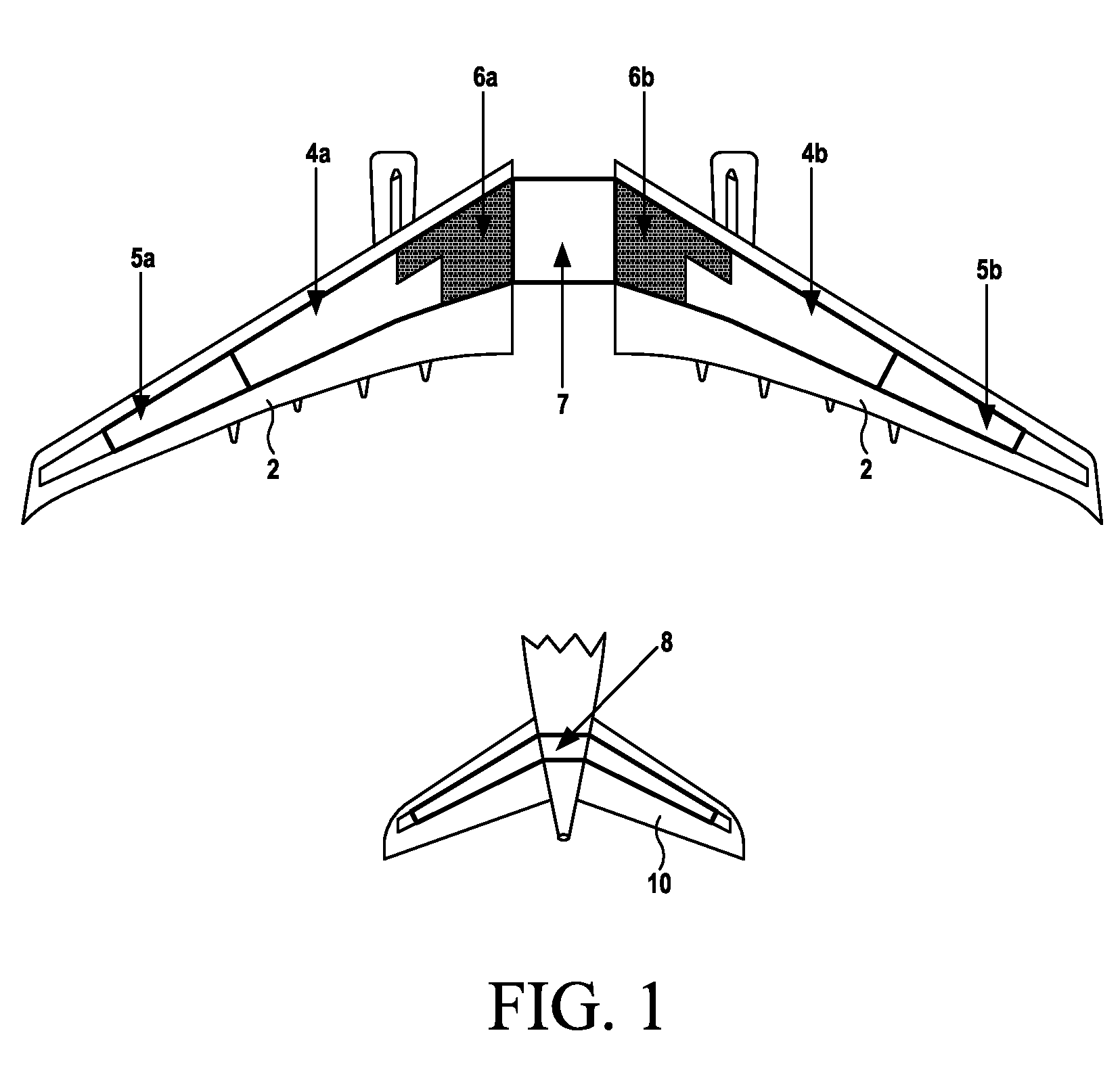
[0020]A typical arrangement of the individual fuel tanks within an aircraft fuel system is schematically illustrated in FIG. 1, with only those parts of the aircraft containing the fuel tanks, i.e. the wings and tail section, being illustrated for clarity. Located within the wings 2 of the aircraft are two pairs of fuel tanks (four individual tanks in total), an inner pair 4a, 4b and an outer pair 5a, 5b. Also located within the wings are two further tanks 6a, 6b from which the fuel actually fed to each engine is taken. These tanks are referred to as the feed tanks. Typically, the majority of the fuel carried by the aircraft is held within the wing tanks. A single central tank 7 is located within the fuselage of the aircraft between the wings. Additionally a single trim tank 8 is located in the tail section of the aircraft, and more particularly in the horizontal stabilisers 10. It will be appreciated that the illustrated fuel tank arrangement is shown purely as an example and other...


PUM


Abstract

A method of controlling the centre of gravity of an aircraft having a plurality of fuel tanks, the method comprising transferring fuel from one or more of the fuel tanks according to a predetermined sequence, the timing of the sequence being dependent on the decrease in gross weight of the aircraft.

Description

FIELD OF THE INVENTION[0001]The present invention relates to a method of controlling the gross weight centre of gravity (GWCG) of an aircraft by adopting a predetermined fuel transfer sequence dependant on the change in gross weight of the aircraft.BACKGROUND TO THE INVENTION[0002]In aircraft with multiple fuel tanks it is common practice to automatically transfer fuel between individual tanks during a flight as the fuel is used. Whilst the control of the fuel transfers will depend on the amount of fuel in the various tanks, other factors may also be taken into consideration. One such factor is the gross weight centre of gravity (GWCG) of the aircraft. As fuel is used the GWCG can move fore or aft along the central axis of the aircraft. If the GWCG is allowed to move beyond certain limits the ability of the pilot to control the aircraft can be impaired. The transfer of fuel between different tanks in the aircraft is used to control the movement of the GWCG and prevent the fore and a...

Claims


Application Information

Patent Timeline
IPC IPC(8): B64C17/10
CPCG01M1/127B64C17/10
Inventor SPOTTISWOODE, MICHAELBURCKHART, ANTOINESJUNGARGARD, PETTER
Owner AIRBUS OPERATIONS LTD
Why Eureka
Try Eureka