Wind power plant and wind-power-plant control method

Inactive Publication Date: 2011-09-22
MITSUBISHI HEAVY IND LTD
View PDF11 Cites 16 Cited by
  • Summary
  • Abstract
  • Description
  • Claims
  • Application Information

AI Technical Summary

Benefits of technology

[0028]According to the present invention, a beneficial effect is afforded in that electric power can be controlled so as to meet the dema

Problems solved by technology

However, when a rotor head having blades is rotated, acoustic noise is generated in some cases, and, in these

Method used


Image

  • Wind power plant and wind-power-plant control method
  • Wind power plant and wind-power-plant control method
  • Wind power plant and wind-power-plant control method

Examples


Example

[0040]An embodiment of the present invention will be described below.

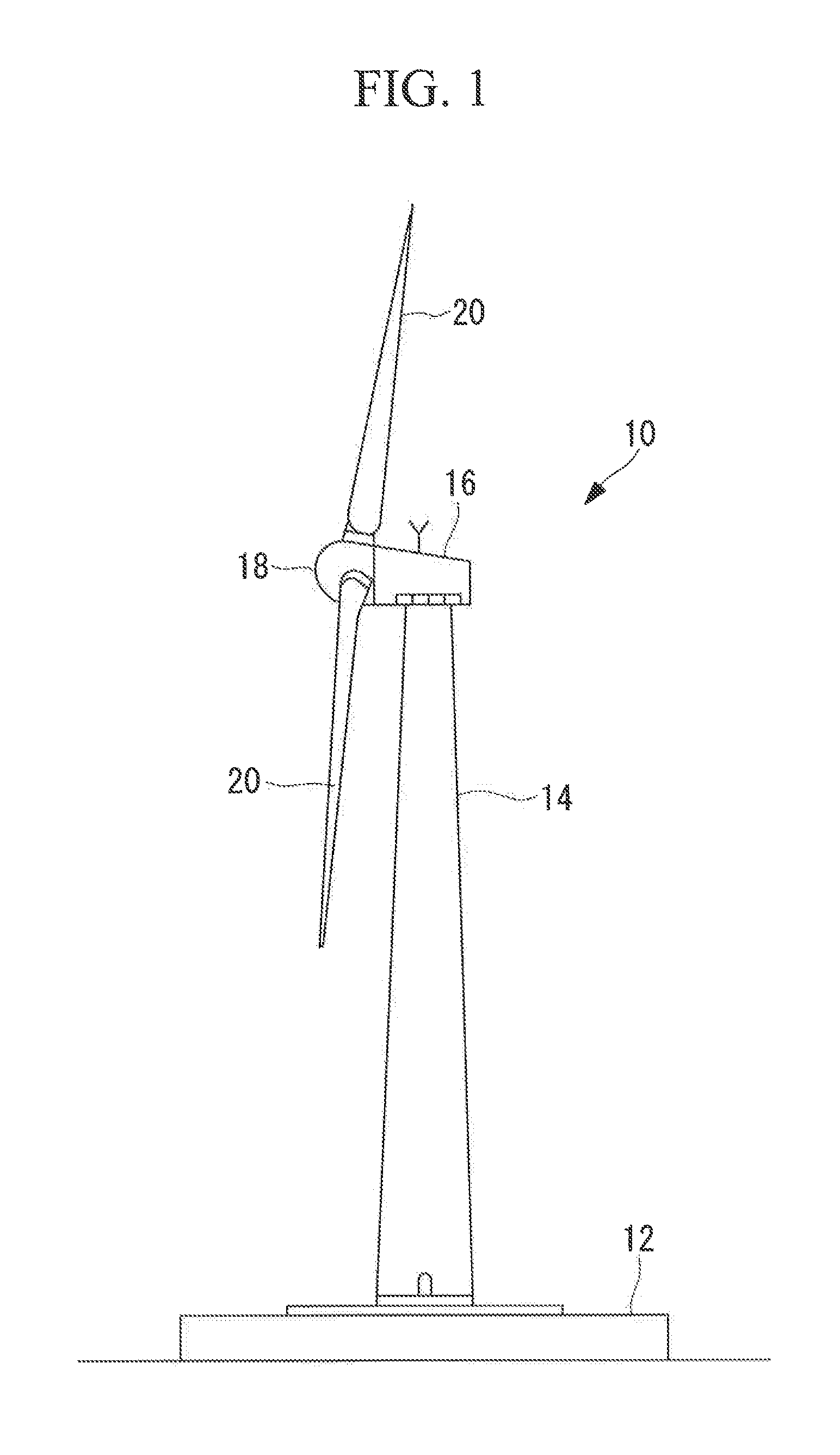
[0041]FIG. 1 is an external view of a wind turbine generator 10 according to this embodiment.

[0042]The wind turbine generator 10 shown in FIG. 1 has a tower 14 provided upright on a foundation 12, a nacelle 16 provided on the top of the tower 14, and a rotor head 18 provided on the nacelle 16 so as to be able to rotate about a substantially-horizontal axis.

[0043]A plurality of (in this embodiment, for example, three) wind-turbine rotor blades 20 (hereinafter, simply referred to as “blades 20”) are attached to the rotor head 18 radially from the rotational axis of the rotor head 18. With this structure, a wind force striking against the blades 20 from the direction of the rotational axis of the rotor head 18 is converted to mechanical power for rotating the rotor head 18 about the rotational axis, and the mechanical power is converted to electric power by a generator. The blades 20 are coupled to the rotor head 18 s...


PUM


Abstract

A wind power plant includes a wind turbine generator and an electrical storage device that supply electric power to a utility grid. A wind-turbine controller performs for the wind turbine generator an acoustic-noise suppression operation in which the rotational speed of blades is controlled in order to suppress acoustic noise, and also calculates a reduction in output power that is the difference in output power between the normal output power and the acoustic-noise-suppression output power. An electrical-storage-device controller causes the electrical storage device to be charged or discharged, based on the reduction in output power, the acoustic-noise-suppression output power, and the grid-demanded output power demanded from the utility grid. Therefore, the wind power plant can supply, to the utility grid, the electric power demanded from the utility grid even when the operation of suppressing the occurrence of acoustic noise is performed for the wind turbine generator.

Description

CROSS REFERENCE TO RELATED APPLICATIONS[0001]This is a continuation of International Application PCT / JP2011 / 052885, with an international filing date of Feb. 10, 2011, which is hereby incorporated by reference herein in its entirety.TECHNICAL FIELD[0002]The present invention relates to a wind power plant and a wind-power-plant control method.BACKGROUND ART[0003]Wind turbine generators, which convert wind force to electric power, are operated in various locations, including locations adjacent to areas where acoustic noise is regulated. However, when a rotor head having blades is rotated, acoustic noise is generated in some cases, and, in these cases, the acoustic noise needs to be suppressed (reduced).[0004]A conceivable method of suppressing the acoustic noise is to reduce the tip speed of the blades. To reduce the tip speed, the rotational speed of the blades needs to be reduced.[0005]In order to suppress the acoustic noise, an acoustic-noise suppression operation for reducing the ...

Claims


Application Information

Patent Timeline
IPC IPC(8): H02P9/04F03D9/02
CPCF03D7/0296F03D7/042Y02E10/723F05B2260/96F05B2270/333F03D9/021F03D9/11Y02P90/50F03D9/255Y02E10/72Y02E70/30Y02E10/76
Inventor YASUGI, AKIRAYANO, KASUMI
Owner MITSUBISHI HEAVY IND LTD
Why Eureka
Try Eureka