Electromagnetic clutch

a technology of electromagnetic clutch and rotor, which is applied in the direction of magnetically actuated clutches, mechanical equipment, wing accessories, etc., can solve the problems of affecting the transmission speed of the clutch, the armature sliding and rotating relative to the rotor, and the need for a large number of caulking pins, so as to avoid plastic deformation of the plate spring member and minimize the delay in initial transmission speed

Inactive Publication Date: 2011-09-22
AISIN SEIKI KK
View PDF6 Cites 8 Cited by
  • Summary
  • Abstract
  • Description
  • Claims
  • Application Information

AI Technical Summary

Benefits of technology

[0055]Then, in the case of the electromagnetic clutch of the above construction, there is provided the rotation restricting member between the armature and the worm wheel. With this, if the worm wheel is to be rotated excessively relative to the armature, the relative rotation of the worm wheel is restricted to the predetermined angle, so that such plastic deformation of the plate spring member can be avoided advantageously.
[0056]Further, since the worm wheel and the armature can contact each other in a reliable manner via the rotation restricting member, once the contact therebetween established, no delay in the transmission speed of the rotational force will occur thereafter. That is, the delay in the initial transmission speed can be minimized.

Problems solved by technology

In this, however, when the electromagnetic clutch is under the non-powered state, the contact force from the armature against the rotor is not so strong.
So, when the opening / closing operation of the vehicle door is effected manually, this will cause the armature to slide and rotate relative to the rotor.
Hence, this requires a great number of caulking pins, screws, etc.
For these reasons, the electromagnetic clutch disclosed in Patent Document 1 requires significant time and labor for its manufacture and high manufacture costs also.
However, since this electromagnetic clutch uses the simple fixing arrangement relying on the engagement of the retaining portion of the armature in the cutout defined in the worm wheel, there is formed a significant amount of looseness (play amount) between the worm wheel and the armature.
For this reason, transmission delay tends to occur in the transmission of drive force between the worm wheel and the armature, which in turn may lead to a trouble at the time of opening / closing of the vehicle door, depending on the control condition.
For instance, in detection of a foreign object jam, this detection takes a long time.
Hence, when the vehicle door is opened / closed manually, a noise tends to be generated due to friction between the armature and the rotor.
This is another drawback of the above electromagnetic clutch.
Therefore, this construction requires a space for laying out the lead wire.
For these reasons, the assembly of the electromagnetic clutch tends to be complicated and requiring greater numbers of parts and manufacturing steps.
As a result, the final product tends to occupy a large space for its mounting and higher manufacture costs as well.
For this reason, this suffers the same drawback as the power supply unit disclosed in Patent Document 2.
Therefore, a foreign object or material such as an amount of grease applied to the worm wheel tends to adhere to the slip ring, thus tending to invite a conduction trouble such as short circuiting.

Method used


Image

  • Electromagnetic clutch
  • Electromagnetic clutch
  • Electromagnetic clutch

Examples


Embodiment Construction

[0069]Next, an embodiment of the present invention will be described with reference to the accompanying drawings. Incidentally, it is understood that the present invention is not limited to the embodiment described below and constructions and arrangements equivalent thereto are intended to be encompassed within the scope of the invention.

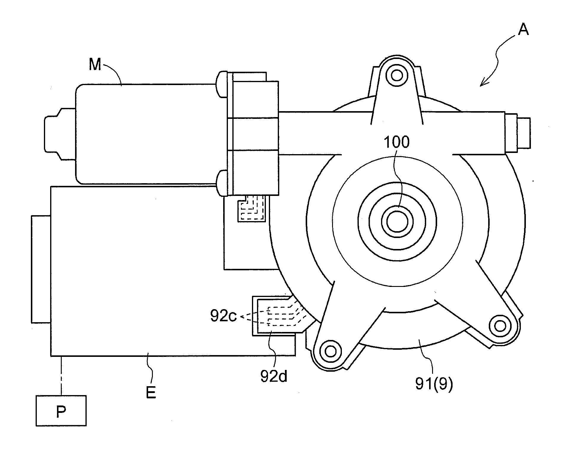
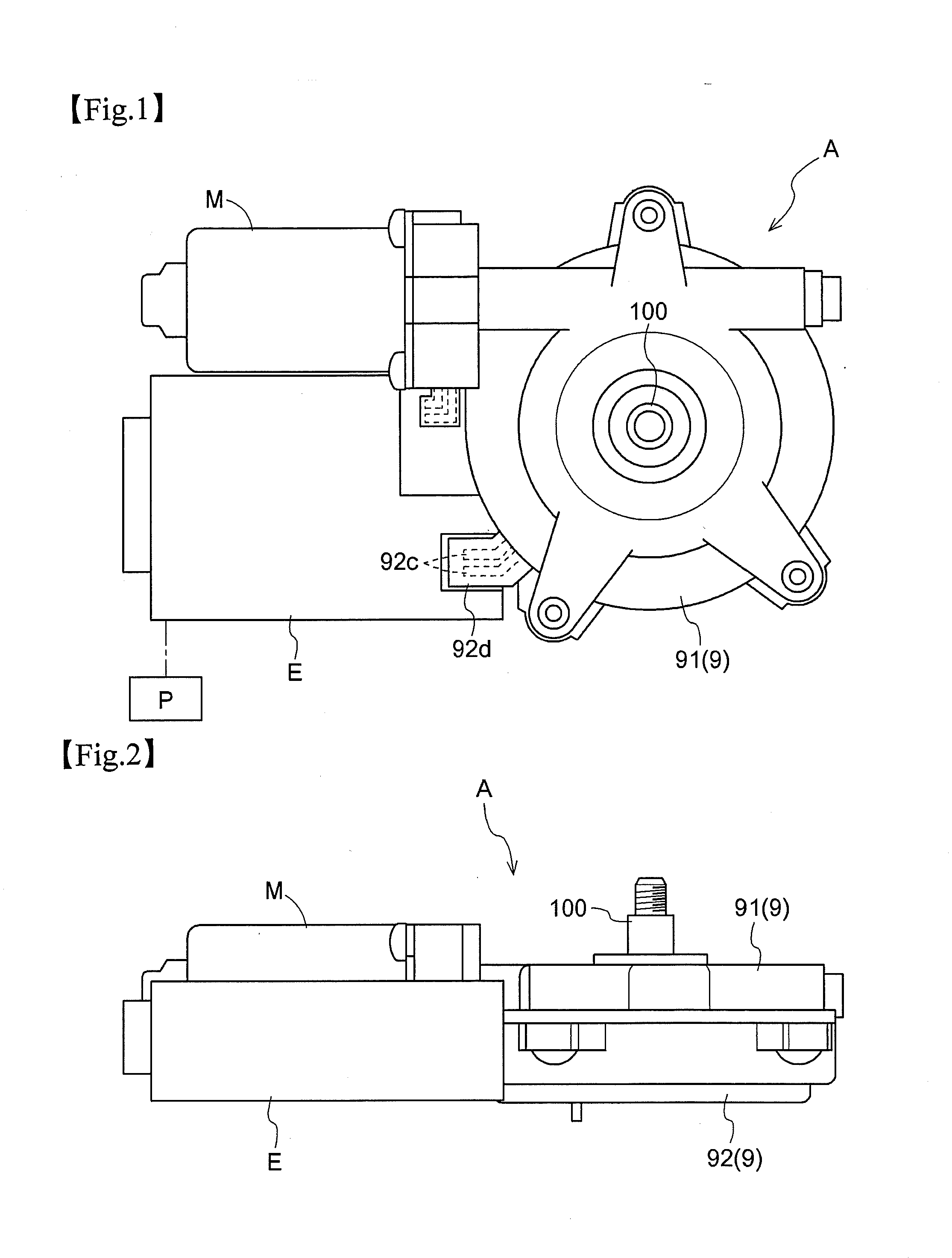
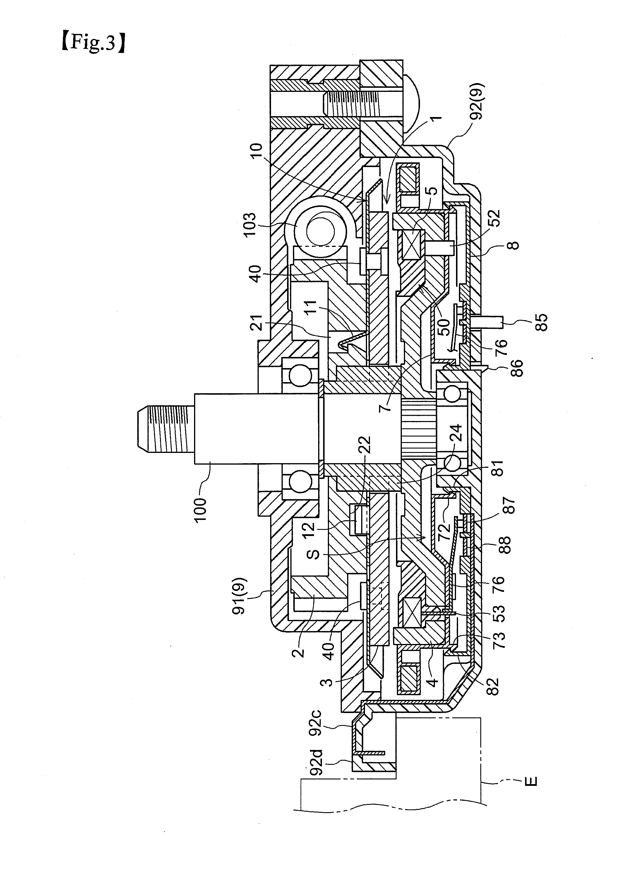
[0070]FIG. 1 is a plane view of a vehicle door opening / closing apparatus implementing an electromagnetic clutch according to the present invention. FIG. 2 is a side view of the vehicle door opening / closing apparatus, and FIGS. 3 and 4 are side views in section showing principal portions of the vehicle door opening / closing apparatus.

[0071][General Construction of Vehicle Door Opening / Closing Apparatus]

[0072]As shown in FIGS. 1-4, the vehicle door opening / closing apparatus A implementing the electromagnetic clutch 1 according to the present invention includes an electric motor M as a drive source for the vehicle door, the motor M being disposed inside...


PUM


Abstract

An electromagnetic clutch includes a motor, a worm wheel rotatably driven by a motor, a rotor having an electromagnetic coil and rotatable about a same rotational axis as the worm wheel, an armature that is mounted to the worm wheel and is pulled into contact with the rotor upon application of electric power to the electromagnetic coil, so that the armature is rotated with the rotor, a cover member configured to cover the rotor and the armature, and a power supply mechanism disposed between the cover member and the rotor and connected to a power source for supplying power to the electromagnetic coil. The power supply mechanism includes a fixed frame body having a first power supply portion for receiving the power from the power source and fixed to the cover member, a rotary frame body having a second power supply portion in contact with the first power supply portion for supplying the power to the electromagnetic coil, the rotary frame body being fixed to the rotor and rotatably engaged with the fixed frame body; and a plate-like conducting member provided in the cover member, the conducting member coming into contact with a portion of the first power supply portion projecting from the fixed frame body.

Description

TECHNICAL FIELD[0001]The present invention relates to an electromagnetic clutch including a worm wheel rotatably driven by a motor, a rotor having an electromagnetic coil, and an armature that is mounted to the worm wheel side and is pulled into contact with the rotor upon application of electric power to the electromagnetic coil, so that the armature is rotated with the rotor.BACKGROUND ART[0002]As an electromagnetic clutch for use in an opening / closing apparatus for a vehicle door, there is known e.g. one having a worm gear, a worm wheel, an armature, a plate spring, a rotor, an electromagnetic coil, etc (see e.g. Patent Document 1).[0003]With such electromagnetic clutch, at the time of non-powered state with no application of electric power to the electromagnetic coil, the armature and the rotor are either spaced apart from each other or in light contact with each other, so as to alleviate a force needed for a manual operation of the vehicle door. At the time of powered state wit...

Claims


Application Information

Patent Timeline
Patent Type & Authority Applications(United States)
IPC IPC(8): H02K7/108
CPCE05Y2201/216E05Y2201/246E05Y2201/462E05Y2900/531E05F15/611H02K5/141H02K7/1085H02K7/1166F16D27/06
Inventor ISHIDA, TOSHIHIKOTAKEUCHI, TSUTOMUOKU, NAOYA
Owner AISIN SEIKI KK
Why Eureka
Try Eureka