Eddy-current magnetic controlled loading device used in a magnetic controlled power generator

a magnetic controlled power generator and loading device technology, applied in the direction of motor/generator/converter stopper, dynamo-electric converter control, dc motor stopper, etc., can solve the problems of large volume and heavy need to be improved, and large volume of the aforesaid rotor, so as to simplify the manufacturing process reduce the volume and weight of the magnetic controlled power generator

Inactive Publication Date: 2011-09-22
SHIHLIN ELECTRIC & ENG CORP
View PDF6 Cites 5 Cited by
  • Summary
  • Abstract
  • Description
  • Claims
  • Application Information

AI Technical Summary

Benefits of technology

[0014]In practice, the diameters of the flywheel, the rotor and the stator are minified so as to reduce the volume and weight of the magnetic controlled power generator. In t

Problems solved by technology

However, some defects exist in the structural relationship between the aforesaid rotor 13 and stator 16.
This leads to very large volume and heavy weight

Method used


Image

  • Eddy-current magnetic controlled loading device used in a magnetic controlled power generator
  • Eddy-current magnetic controlled loading device used in a magnetic controlled power generator
  • Eddy-current magnetic controlled loading device used in a magnetic controlled power generator

Examples


Embodiment Construction

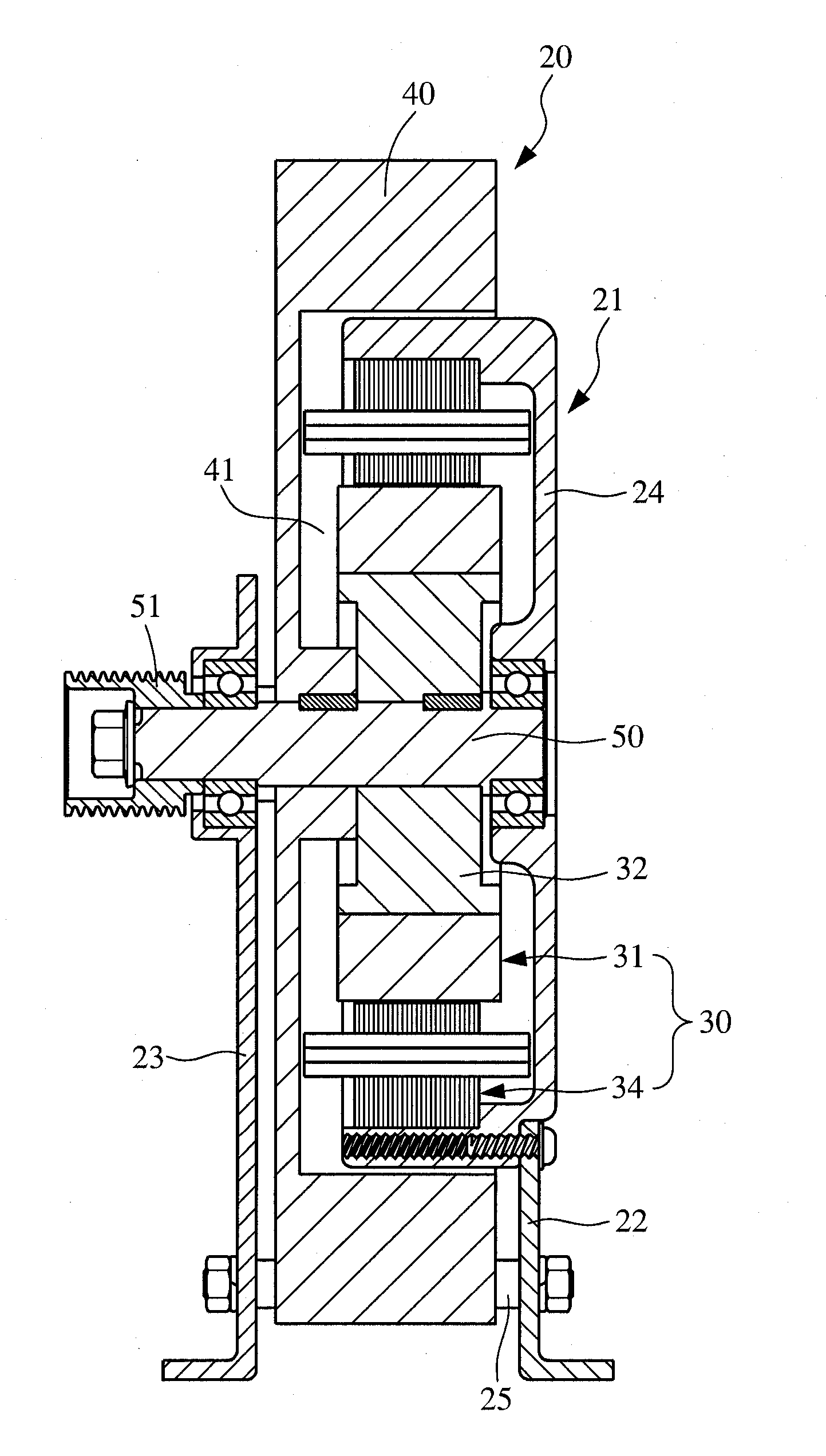
[0021]FIGS. 2 and 3 respectively are a sectional view and a perspective exploded view of the eddy-current magnetic controlled loading device used in the magnetic controlled power generator of the present invention. Please refer to FIGS. 5 and 6. The magnetic controlled power generator 20 includes: a frame 21; an eddy-current magnetic controlled loading device 30; a flywheel 40 formed with vents as a fan for air circulation and enhancement of heat dissipation efficiency; a rotary axle 50; and a magnetic controlled device 60. The frame 21 has a first bracket 22 and a second bracket 23. A reception body 24 is connected to a top end of the first bracket 22. The first and second brackets 21, 22 are interconnected by means of a plurality of fastening rods 25 with the same length. The flywheel 40 has an internal circular cavity 41 with a hub section 42. The hub section 42 has a passage 43 dimensionally adapted to receive the rotary axle 50. The rotary axle 50 passes through the required be...


PUM


Abstract

An eddy-current magnetic controlled loading device used in a magnetic controlled power generator, including a frame, an eddy-current magnetic controlled loading device, a flywheel, a rotary axle for supporting the flywheel, and a magnetic controlled device. The eddy-current magnetic controlled loading device includes: a rotor coupled to the rotary axle and positioned in the flywheel, the rotor having a rotor core and several pieces of permanent magnets arranged on outer circumference of the rotor core, the rotary axle being rotatable to drive and rotate the flywheel and the rotor; and a stator fixed on the frame and coaxially disposed outside the rotor. The stator has a stator core and multiple radial projections arranged on inner circumference of the stator core. A gap between crown sections of the projections is smaller than a gap between root sections of the projections, whereby a previously wound coil can be fitted onto the projections.

Description

BACKGROUND OF THE INVENTION[0001]1. Field of the Invention[0002]The present invention relates generally to an eddy-current magnetic controlled loading device, and more particularly to an eddy-current magnetic controlled loading device used in a magnetic controlled power generator.[0003]2. Description of the Related Art[0004]There are various conventional exercise equipments including treadmills, exercise bikes, steppers, etc. In operation of any such exercise equipment, a user can use his / her feet, hands or other parts of the body to move an operation mechanism of the exercise equipment, (for example, the track of a treadmill, the sprocket of an exercise bike, the pedals of a stepper, the handles of a power rower). The operation mechanism then drives a flywheel to rotate. When operating the exercise equipment to simulate running, stepping or rowing, under the inertia of the flywheel, the load exerted on the user can be increased to enhance exercise intensity.[0005]In order to meet t...

Claims


Application Information

Patent Timeline
IPC IPC(8): H02P3/14
CPCH02P3/04H02K49/043
Inventor LEE, MING-YUHUANG, YU-HSING
Owner SHIHLIN ELECTRIC & ENG CORP
Why Eureka
Try Eureka